t1muk4s
Newbie level 1
Hello!
I have a problem with a fan controller. The controller is able to regulate the voltage to the fan from 7 to 15 volts DC (speed regulation).
Also the controller is switching the voltage in the output from one output to the other so that the fan is able to spin in both directions (it switches the negative part of the output).
The fan has three wires so i assume that it has two coils.
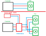
I need to connect more fans to the controller, but the controller is only able to control 50W of fans. My goal is to boost somehow it to 300 or more watts.
I added a simple sketch to show the system.
What kind of solution is for this problem (so that the speed regulation works with the new switch block)?
Best wishes,
T.
