Continue to Site

Welcome to EDAboard.com

Welcome to our site! EDAboard.com is an international Electronics Discussion Forum focused on EDA software, circuits, schematics, books, theory, papers, asic, pld, 8051, DSP, Network, RF, Analog Design, PCB, Service Manuals... and a whole lot more! To participate you need to register. Registration is free. Click here to register now.

DC-DC, synchronous rectifier

Status
Not open for further replies.

Adri67

Junior Member level 2
Joined
Aug 11, 2014
Messages
24
Helped
0
Reputation
0
Reaction score
0
Trophy points
1
Activity points
267
Hello !
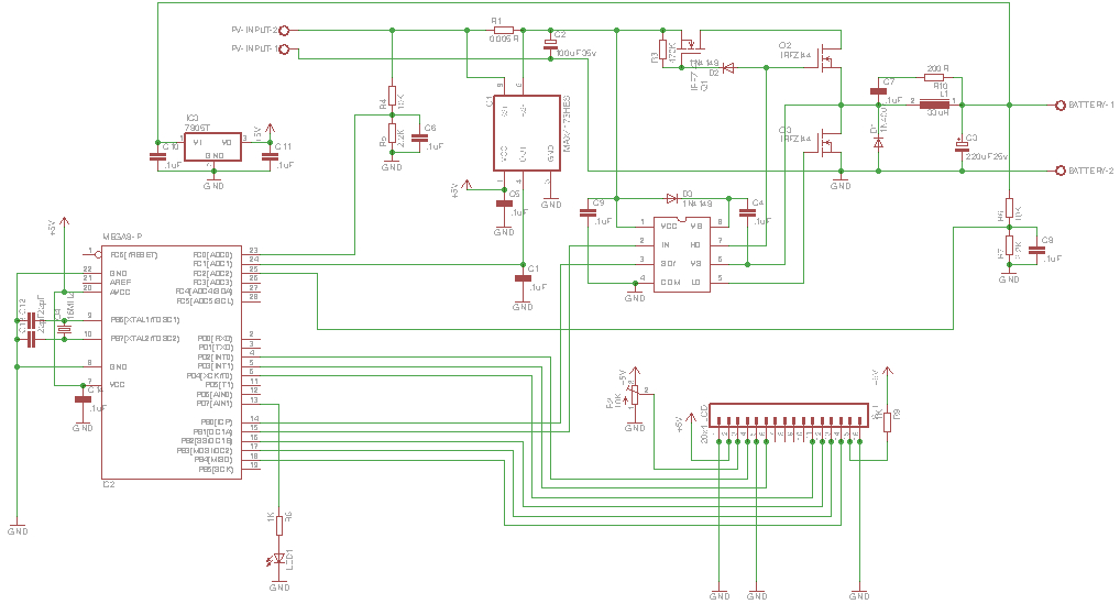
I have a problem understanding how the SR (synchr.rectifier) Q3 functions.
I'm okay with the first uS's after Q1 & Q2 have turned off and Q3 conducts unloading L1 cia C3, i.e. improved job that D1 does.
But what happens then?
The way I understand it is that seeing that the MOSFET is bi-directional when switched on, the device effectively short-circuits the output (and the battery).
Or perhaps that L1 is so large that it keeps supplying current during the entire "on-period" of Q3.
What am I reading wrong or missing?
Thanks in advance
 

Attachments

  • TimNolan.pdf
    114.3 KB · Views: 62

Your assesment is correct, the lower mosfet , as long as gate drive is applied, will conduct current both ways. Unlike a real diode, which intrinsically only conducts one way.

The better synchronous rectifier drivers have a diode emulation mode, whereas the lower mosfet's gate drive is removed to prevent discharging the capacitor.
There are many ways to achieve this, google diode emulation mode.
 

Reverse current through the inductor may be intended for a synchronous rectifier (forced continuous mode) because it eases the controller design and improves the load step response. But fully synchronous operation is only possible as long as Vin > Vbat. The present circuit also blocks battery discharge for Vbat > Vin, in this case high side and low side driver have to both disabled.

Emulated diode mode (allowing discontinuous buck operation) can be reasonable to increase efficiency for low input power.
 

I took your advice and checked out 'emulated diode' and indeed there's a heap of info.
Alas a lot confuses me.
The short answer that comes to mind is this :
a. measure volts on both sides of L
b. while V higher on left side (incoming) of L than right side (i.e. L is ready/going to conduct/charge the C) AND Q1/Q2 is off, turn on Q3 (with a slight delay to prevent possible shoot-through), and ensuring rapid turn-off when the difference is 0 or close to 0.
My thinking is that Q3 is then doing nothing more or less than emulating the Schottky diode in parallerl with it.
If this is right then making it work with a Arduino ProMini at high frequency (say 500 KHz) could be tricky regarding the internal ADC response.

Two (or more) questions in one go!
Your opinion, please.

Have I stumped everyone?
Any ideas of how to get synch. rectifier to work?
 

As previously mentioned the said "emulated diode mode" is not necessary. I presume, you have implemented synchronous rectification for better efficiency at higher current. A possible reason to disable it could be that you are running at low current for longer time amounts.

The usual way to switch off the low side FET and allow transition to discontinuous mode is by detecting the current reversal in the low side FET. As you don't have this feature in your hardware, the method can't be applied in your circuit.

A possible solution could be to enable synchronous rectification above a certain input current level (as measured with the shunt) and switch to asynchronous rectification at low current.
 

Status
Not open for further replies.

Similar threads

Part and Inventory Search

Welcome to EDABoard.com

Sponsor

Back
Top