ahmedmedowahdan
Member level 1
i bought alot of IRF9540n ICs 
i need suitable solutions for my problems
- - - Updated - - -
i need suitable solutions for my problems
- - - Updated - - -
Follow along with the video below to see how to install our site as a web app on your home screen.
Note: This feature may not be available in some browsers.
you talked about n-mosfetdriver can not drive p-channel mosfet's.
if you want to use a mosfet as switch . and you want to turn on mosfet then gate need Vgs of approximately 10v .
and when you want to turn off mosfet then gate need Vgs of 0v or -ve voltages if possible.
when you use mosfet as high side switch and turn it on then drain voltages passes through mosfet and goes to source.
now source voltages are equal to vd (drain voltage ). and now gate shuld have Vgs of 10v . so you need Vcc+10 now.
this ic solves this problem by using charg pump technique.
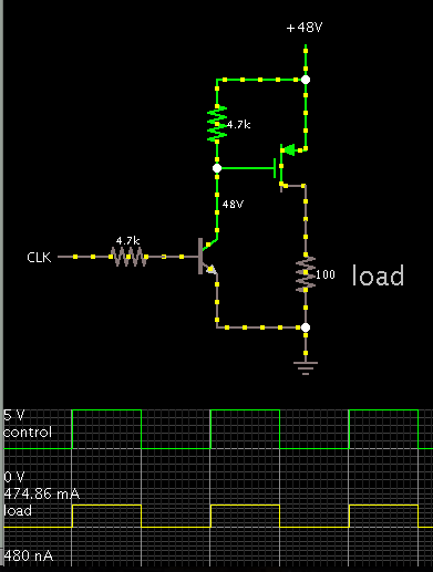
vgs max = +/- 20 vHere is a way to drive a P-mosfet, so that it conducts when the control signal is positive.
During On-time, the gate level is pulled close to 0V, which is sufficient to turn it on.
During Off-time, the gate automatically receives 48 V, which is the volt level needed to turn it off.
The additional transistor might cause a small delay in the action. This could make a difference when operating frequency is very fast.

can i replace

what is rate of power >>> output voltage*current or input voltage*current??
can i replace
ir2101 with ir2110
what is high freq diode
is ther capacitor of .1uf value?
What watt size of resistors?( is there high watt resistors?)
capacitor you mean is bootstrap cap ?1 : Yes you can use ir2110.
2 : Fast recovery diode. More examples example fr 207 , fr307
3 : Capacitor shuld 1uf .
4 : Resistor shuld 2/w minimum.