sabu31
Advanced Member level 1
Hi all,
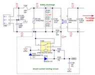
I am trying to implement a current limit circuit using a Relay. I am following the circuit mentioned by TI instruments as attached. As I dont have the exact circuit components, i have replaced the diode in the circuit with 1N4007. The relay used is Song Chuan (832A-1A-C-BH-12VDC) and for the 12 V supply, I am using the Hi Link 12V (5W) supply.
However, when using 75k diodes and 12 V Zener along with a diode (1n4007) as mentioned in the circuit diagram, the circuit does not work.
But simply connecting the 12 V supply and 1N4007 (as freewheel) works. What could be the reason? The rise time for the 12 V supply is 5ms. Is 5ms enough to limit in-rush current?