mathewgood
Newbie
Hello, I have this old CRT Sony F900 monitor, and I have been using him every day for the past 20 years. All I am asking, if possible, for a tip, on where I should start my investigation, my knowledge about the signal process in CRT is marginal.
The most recent measurements around IC620 MCZ3001D SW REG CONTROL are on the very bottom.
The link to the service manual is here https://drive.google.com/file/d/1D-sZZZDAH7SM4-e3q_wcBfSZUcg4pnRc and in the attachment.
I was trying to reach many places before I decided to write to you. At this point, I understood, from the people and services I have tried to contact no one would even like to talk about CRT monitors.
I wish to know how to think and locate a failing component. I will put all my efforts to learn and contribute. I can make measurements in any state, check anything you would suggest, and record videos from the measurements. If you would like to go with me on this journey I would be thrilled. I have some knowledge mainly from your electronic repair guide blog, crt youtube repairs, and forums post, I just have a big mess in my head.
How it started
- I have dissembled him and could not find any burned, discolored, odd electronic elements.
- I couldn't spot any cold joints with a magnifying glass.
- Tube, Flyback, and caps are unlikely the issue (the guy who is having the same symptoms on the video had replaced every single cap across all of the boards)
- Heating up is not helping anymore
[Voltages that are going out from the G board when the monitor is powered on]
CN651
7V = 7V
CN650
STB5V = 5V
1W5V = 5V
ECO SW = 5V -> po chwili 3.5V
HTR SW = 4.9V
DGUSSW = 4.8V -> 0V
PWR SW = 5V
CN652
STBY5V = 5V
1W5V = 5V
+80V = ~15V for 1/2s -> 0V
+220V = ~90V-200V for 1/2s -> 0V
+12V = ~3.43V for 1/2s -> 0.04V
HEATER = 5V
CN653
+15V = ~1.36V for 1/2s -> 0.02V
-15V = ~2.43V for 1/2s -> 0.02V
+80V = ~3.8V for 1/2s -> 0V
CN653
H CENT H = ~4.3V for 1/2s -> 0V
H CENT N = ~6.3V for 1/2s -> 0V
H CENT L = ~7.2V for 1/2s -> 0V
+220V = ~15V for 1/2s -> 0V
G2 Voltage on A board = 0.00V
[G board (Power Supply)]
Measurements around IC610
C611 = 420V - (10) CATHODE but according to the Service manual it should be 376V
R643 = 0.0V
R629 = 0.0V
C639 = 9.3V
C648 = 14.8 V
R625 = 0.00V - should be 192V - (16) VG (H) (IC620 MCZ3001D SW REG CONTROL)
Those 2 resistors are on the red line going straight to (8) VC1 (IC620 MCZ3001D SW REG CONTROL)
R631 = 0.9V
R696 = 3.1 V
Out from VCC z IC610 - red line
R614 = 2.5V
C613 = 13.5V
C611 = 250V it is connected to (3) AC SEN IC610 (but in the Service manual it says it should be 86.2 V)
R620 = 0.0V
C643 = 0.15V
R621 = 97.0V
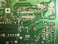
I don't understand what is going on with the R651 resistor, he is not present in any service manual
R651 = 73.0 V (photograph below)

The leg of R651 is connected to (1) V SENSE and the voltage across resistors is
R651 and R621 = 402 V is connected to (1) V SENSE of (IC620 MCZ3001D SW REG CONTROL) but in the service manual is printed it should be there 1.7V
C645 = 2.2V (3) CT - OK - Service manual = 2.2V (IC620 MCZ3001D SW REG CONTROL)
C647 = 0.00V (6) TIMER - OK - Service manual = 0 V (IC620 MCZ3001D SW REG CONTROL)
Here, does it mean that C646 is failing and needs to be replaced?
C646 = 0.17V (7) SS - WRONG - Service manual = 4.5V (IC620 MCZ3001D SW REG CONTROL)
I don't understand why when I am touching with only one prob of the multimeter on the legs of C646 I have 2.7V readings (the 2nd probe is in the air, not touching anything)
C640 = 10.8V (10) VC2 - OK - Service manual = 10.3 V (IC620 MCZ3001D SW REG CONTROL)
C642 - 0.00 V
R625 - 0.00 V
R626 - 0.00 V
The most recent measurements around IC620 MCZ3001D SW REG CONTROL are on the very bottom.
The link to the service manual is here https://drive.google.com/file/d/1D-sZZZDAH7SM4-e3q_wcBfSZUcg4pnRc and in the attachment.
I was trying to reach many places before I decided to write to you. At this point, I understood, from the people and services I have tried to contact no one would even like to talk about CRT monitors.
I wish to know how to think and locate a failing component. I will put all my efforts to learn and contribute. I can make measurements in any state, check anything you would suggest, and record videos from the measurements. If you would like to go with me on this journey I would be thrilled. I have some knowledge mainly from your electronic repair guide blog, crt youtube repairs, and forums post, I just have a big mess in my head.
How it started
- It started with a bright and greenish picture upon starting a cold monitor.
- About 2 years ago, only on the cold boot, the screen started to occasionally flash with a green picture with retrace lines.
- About one year ago, when the screen was flashing on a high resolution I had to switch the input to only the OSD menu because in another case the screen would turn off and the diode would start to blink orange.
- At this point, I started turning on the screen with 640x480 resolution to the moment he will warm up.
- Always after the power station was turning on and off electricity, the issue started to progress. Basically, the electricity was cut off from the monitor a few times in a row in a very short period of time.
- After a few episodes like that, the screen started flashing red instead of green.
- After a few months, it was green and red in a similar proportion. The monitor had to be warmed up by switching INPUT 1/2 to calm him down.
- I have decided to keep him turned on all the time. He was working from one electricity shutdown to another.
- After another episode with electricity, I couldn't power him on. I need to press the power button on and off for 20 minutes to finally succeed.
- At this point, the only way to power him on was by pressing power on and off and changing the inputs from the front panel. He needs to stabilize and I won't do anything he will turn himself off like in this video
- The last few times I was able to power him after heating his back with a hairdryer. When he was turning on he wasn't flashing red or green. He was warmed up.
- At this point, I have stopped trying to power him on. There is a big chance that I would be able to turn him on but in the long run, it's pointless.
- When the monitor will luckily turn on there are absolutely no issues as long as he is displaying the picture. When the monitor will lose power or will go to standby mode it is not working and cannot be turned on.
- When the monitor will somehow turn on it is flashing green, red, or both. It depends on the room temperature.
- If he receives a high-resolution picture from a graphic card (higher voltage needed to operate) he is flashing green and red and goes to the standby mode and cannot be turned on again. He cannot stabilize
- It was required to keep him on 640x480 dpi until he will warm up
- If the back of the monitor was preheated with a hairdryer from the sides and turned on there is no green and red flickering and can instantly operate on higher resolutions with no issues. If he will luckily turn it on.
- When he cannot be turned on and there is no graphic card connected to the monitor the led is green and goes to standby mode. There is no OSD menu displayed at all or green INPUT subtitles on the screen.
- If he has a graphic card (first video input 1) connected, the monitor after a few seconds starts blinking orange - no light - orange no light infinitely. In the video below I am switching from INPUT 2 (no source) to INPUT 1 (VGA source). For BNC sources the same situation. There is no OSD menu displayed at all or green INPUT subtitles on the screen.
- I have dissembled him and could not find any burned, discolored, odd electronic elements.
- I couldn't spot any cold joints with a magnifying glass.
- Tube, Flyback, and caps are unlikely the issue (the guy who is having the same symptoms on the video had replaced every single cap across all of the boards)
- Heating up is not helping anymore
[Voltages that are going out from the G board when the monitor is powered on]
CN651
7V = 7V
CN650
STB5V = 5V
1W5V = 5V
ECO SW = 5V -> po chwili 3.5V
HTR SW = 4.9V
DGUSSW = 4.8V -> 0V
PWR SW = 5V
CN652
STBY5V = 5V
1W5V = 5V
+80V = ~15V for 1/2s -> 0V
+220V = ~90V-200V for 1/2s -> 0V
+12V = ~3.43V for 1/2s -> 0.04V
HEATER = 5V
CN653
+15V = ~1.36V for 1/2s -> 0.02V
-15V = ~2.43V for 1/2s -> 0.02V
+80V = ~3.8V for 1/2s -> 0V
CN653
H CENT H = ~4.3V for 1/2s -> 0V
H CENT N = ~6.3V for 1/2s -> 0V
H CENT L = ~7.2V for 1/2s -> 0V
+220V = ~15V for 1/2s -> 0V
G2 Voltage on A board = 0.00V
[G board (Power Supply)]
Measurements around IC610
C611 = 420V - (10) CATHODE but according to the Service manual it should be 376V
R643 = 0.0V
R629 = 0.0V
C639 = 9.3V
C648 = 14.8 V
R625 = 0.00V - should be 192V - (16) VG (H) (IC620 MCZ3001D SW REG CONTROL)
Those 2 resistors are on the red line going straight to (8) VC1 (IC620 MCZ3001D SW REG CONTROL)
R631 = 0.9V
R696 = 3.1 V
Out from VCC z IC610 - red line
R614 = 2.5V
C613 = 13.5V
C611 = 250V it is connected to (3) AC SEN IC610 (but in the Service manual it says it should be 86.2 V)
R620 = 0.0V
C643 = 0.15V
R621 = 97.0V
I don't understand what is going on with the R651 resistor, he is not present in any service manual
R651 = 73.0 V (photograph below)
The leg of R651 is connected to (1) V SENSE and the voltage across resistors is
R651 and R621 = 402 V is connected to (1) V SENSE of (IC620 MCZ3001D SW REG CONTROL) but in the service manual is printed it should be there 1.7V
C645 = 2.2V (3) CT - OK - Service manual = 2.2V (IC620 MCZ3001D SW REG CONTROL)
C647 = 0.00V (6) TIMER - OK - Service manual = 0 V (IC620 MCZ3001D SW REG CONTROL)
Here, does it mean that C646 is failing and needs to be replaced?
C646 = 0.17V (7) SS - WRONG - Service manual = 4.5V (IC620 MCZ3001D SW REG CONTROL)
I don't understand why when I am touching with only one prob of the multimeter on the legs of C646 I have 2.7V readings (the 2nd probe is in the air, not touching anything)
C640 = 10.8V (10) VC2 - OK - Service manual = 10.3 V (IC620 MCZ3001D SW REG CONTROL)
C642 - 0.00 V
R625 - 0.00 V
R626 - 0.00 V