Continue to Site

Welcome to EDAboard.com

Welcome to our site! EDAboard.com is an international Electronics Discussion Forum focused on EDA software, circuits, schematics, books, theory, papers, asic, pld, 8051, DSP, Network, RF, Analog Design, PCB, Service Manuals... and a whole lot more! To participate you need to register. Registration is free. Click here to register now.

Steinberg UR44 Audio Interface No Power

Joined
Dec 8, 2023
Messages
2
Helped
0
Reputation
0
Reaction score
0
Trophy points
1
Activity points
27
I have a Steinberg UR44 audio interface that I had in storage for a few years, and now that I want to use it doesn't power on. I want to take this opportunity to learn electronics repair so I am trying to repair it for learning experience.

I am looking for guidance on how to proceed with troubleshooting the problem.

I have checked the original power supply with a multi meter and it works.

I visually inspected the PCB board and don't see any issues, except what looks like a possible broken fuse but not sure. I checked it for continuity it reads 97 ohms, but 3 components that light up for a split second when I press the power button on the audio interface when I inspect the PCB board with a thermal camera.


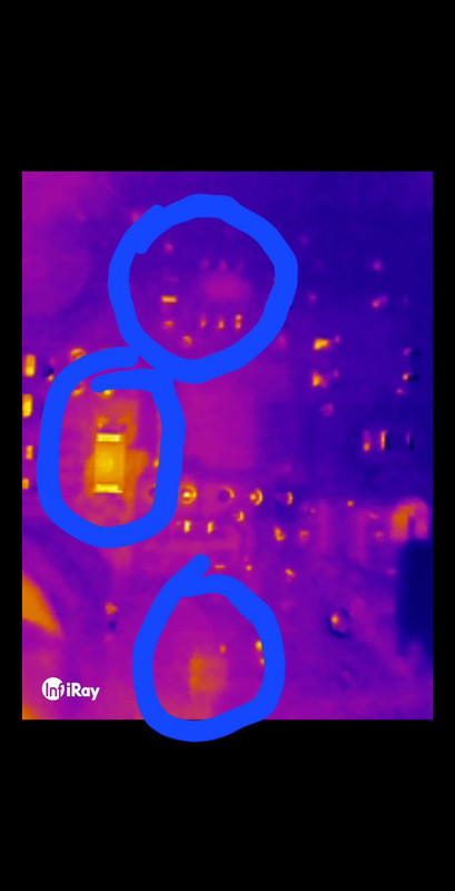
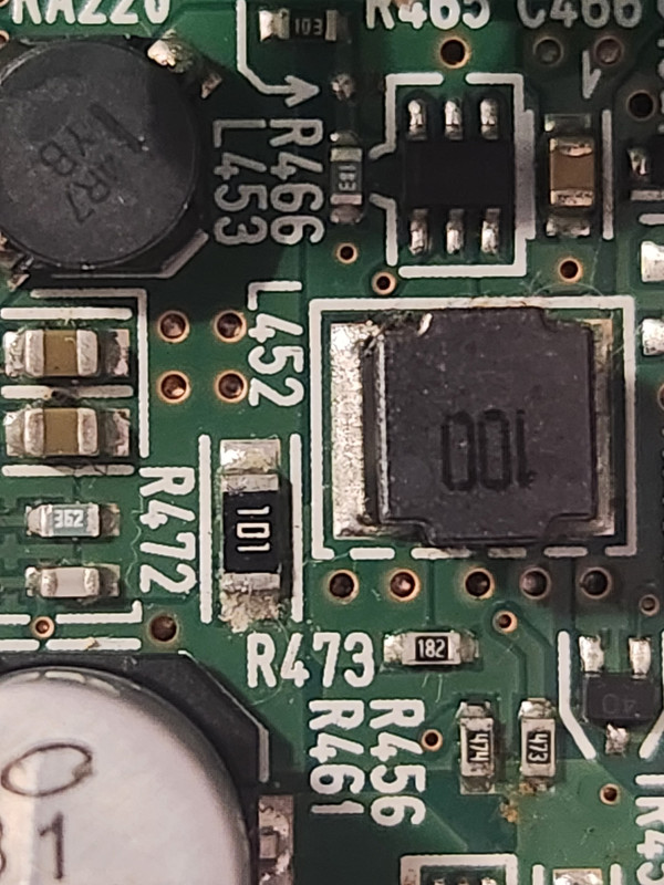
This pictures shows where the power jack is(blue circle), which is right next to the power button, and the barely visible green square shows the area where the 3 components are heating up/lighting up for a split second when inspected with the thermal camera.


I am new to electronics repair, how should I proceed from here in troubleshooting the problem?

Thanks for the help.
 
Those components that "light up", are they SUPPOSED to light up? Are they LEDs, or are they components that are being so over-stressed that they're incandescing? A fuse should not be 97 ohms, it's probably something else. What makes you THINK it's a fuse? Do you have a schematic? Without one it's pretty hard to trouble shoot.

And what do you mean 'the power supply works'? If that's so then what's your actual problem? Don't just say 'it doesn't work'.
 
Hi,

this 100 Ohm resistor is rather large (I would guess 0805) compared to the other installed resistors shown in the picture. So it migth dissipate some power by design. As it is placed gloce to an inductor and an IC, I would guess it acts as a current sensing resistor (a so called shunt) for a SMPS, but its value is "quite high". You made a thermal image, could you share the temperature scale as well, as it might span several tens of degrees or only a couple of degrees.

I agree with @barry 97 Ohms are too high for a fuse. Could you share a picture of the fuse, just to double check what you have tested, as you mentioned you are (at the beginning) learning electroonics.

BR
 
This level of repair is beyond a beginner. It is obsolete so finding a repair guy locally is your best choice, but it may not be cost effective.
the 101 part is a 100 ohm resistor +/-5%

It looks like it has power but is not functional.
 
Those components that "light up", are they SUPPOSED to light up? Are they LEDs, or are they components that are being so over-stressed that they're incandescing? A fuse should not be 97 ohms, it's probably something else. What makes you THINK it's a fuse? Do you have a schematic? Without one it's pretty hard to trouble shoot.

And what do you mean 'the power supply works'? If that's so then what's your actual problem? Don't just say 'it doesn't work'.
Sorry for the late reply. The components on the PCB board that heat up for a split second, I don't think they are suppose to do that. I plug the power supply, tried USB too, to the audio interface, it doesn't turn on or do anything. Its dead. I tested the power supply with a multimeter, it reads 12v, which is what the output should be, also tested the power jack while the power supply was plugged in, also reads 12v.

I am doing research on which ESR meter to get to test the capacitors. This device will probably never work again so its probably going to be used so I can practive soldering/desoldering on it.
 
Hi,

so the "fuse" is of the table? What have you inspected?

What is the temperature scaling of the attached FLIR picture? Heat up might be as expected due to startup inrush current.

There are ICs installed on the board which are for sure not supplied by 12V e.g. the MCU/FPGA and the memory. So there are for sure other voltage regulators creating 5V, 3.3V or 1.8V. Try to find them and check their output voltages.

BR
 

LaTeX Commands Quick-Menu:

Part and Inventory Search

Welcome to EDABoard.com

Sponsor

Back
Top