Continue to Site

Welcome to EDAboard.com

Welcome to our site! EDAboard.com is an international Electronics Discussion Forum focused on EDA software, circuits, schematics, books, theory, papers, asic, pld, 8051, DSP, Network, RF, Analog Design, PCB, Service Manuals... and a whole lot more! To participate you need to register. Registration is free. Click here to register now.

Counting system using optical technology

Status
Not open for further replies.

Navankur Verma

Newbie level 3
Newbie level 3
Joined
Nov 7, 2014
Messages
4
Helped
0
Reputation
0
Reaction score
0
Trophy points
1
Location
Indore
Visit site
Activity points
31
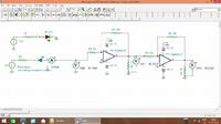
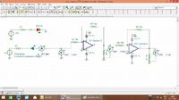
We are doing a project on counting the number of people crossing through a doorway,in which we have used an IR LED n PHOTODIODE which makes a change in current from photodiode when a person crosses, and this current is supplied to two inverting amplifiers using OP AMP IC 741 which produces nearly +5V when no obstruction is caused and nearly 200 mV when it is.
These pulses are given to the clock of counter IC 4033 which shoul have incremented the count every time a person passes BUT IT IS NOT DOING SO and the decoded outputs for 7 segement display of the IC are giving the correct results.
Can any body suggest about solving this problem?
And we think that we are doing some mistake in using 4033 IC but not able to rectify it?
So need your help we have to submt this one before 20th november!!
Thanks

Posted via Topify on Android
 

The old CD4033 uses positive logic active inputs, so ensure all inputs are low , not floating and use rising edge of clock.

Ensure clock as no spurious edges by using hysteresis or at least 10% positive feedback in comparator (741) or enough to exceed input ripple from slow motion. Sometimes filtering and/or a one-shot is used to prevent multiple counts within 0.xx sec.
 

Thanks for the reply
But how can we create rising edge?
Because it remains +5V when idle and goes low when obstruction passes?
And are you sure about keeping all required pins low of 4033?

Posted via Topify on Android
 

Please post your schematic. There may be voltage level problems, the 741 needs a higher supply voltage than 5V to work properly and the CD4033 can need as much as 10V at its inputs if it runs on a 20V supply. The positive/negative edge should not make much difference, it will just count the beam being restored rather than interrupted.

Brian.
 

Thanks Brian
Yes we r giving +15V & -15 supply to 741opamp ic correctly.
But I have doubt that the 10V input u r saying about giving to 4033 is for clock IN or the Vdd supply?
We tried with Vdd @5V and clock IN with 200mV for low and 4.5V for high but still it didn't worked.
And I will share my schematics and circuit on breadboard by tomorrow.
Thanks again.

Posted via Topify on Android


Here is the link for schematics and also the TINA model fie of circuit
 

Attachments

  • dtct+opamp CTR drivable+inverted.zip
    2.4 KB · Views: 108

Status
Not open for further replies.

Part and Inventory Search

Welcome to EDABoard.com

Sponsor

Back
Top