Continue to Site

Welcome to EDAboard.com

Welcome to our site! EDAboard.com is an international Electronics Discussion Forum focused on EDA software, circuits, schematics, books, theory, papers, asic, pld, 8051, DSP, Network, RF, Analog Design, PCB, Service Manuals... and a whole lot more! To participate you need to register. Registration is free. Click here to register now.

Cooling fan that looks like a resistive load?

Status
Not open for further replies.
T

treez

Guest
We are looking for a 48VDC (25W) Axial fan to cool our electronics with. We need it to look like a resistive load so that we can supply it from a small value ceramic capacitor as we do not want any electrolytic caps on the PCB.
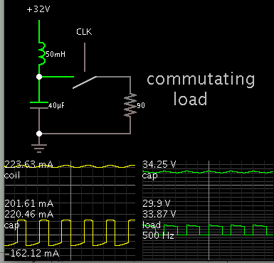
As you know, many BLDC fan motors do not actually have “high frequency PWM” controlled fan coil current, -rather they simply have “commutation PWM’’ which switches from one coil to the next in order to spin the fan.
As you know, if there is no “high frequency PWM” acting on the fan coils, then the fan coils can resonate with the supply capacitor if the supply capacitor is not big enough, and to be that big the supply capacitor has to be an electrolytic one, which we do not want. As you know, if the fan coil commutation period is greater than the LC resonant frequency of the fan coil inductance and supply capacitor, then the resonance causes problems for driving the fan.
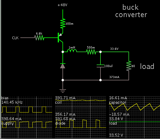
Do you know of any fans which have the high frequency PWM’ing of the fan coils such that the fan coils effectively look like resistive loads from the supply capacitors point of view?

As you can see on page 3 of the following, the current in most brushless dc fans is highly resonant, this causes much ripple current in the supply capacitor...the resonant appearance to the waveform that you see on page 3, is actually the fan coil inductance resonating with the supply capacitance.

https://www.nmbtc.com/pdf/engineering/cooling_fan_behavior.pdf
 
Last edited by a moderator:

I guess this is the same fan that was to go with a buck converter?

There is a way you can operate a buck converter, with only a tiny capacitor. That is (a) with a coil of a larger-than-usual Henry value, and (b) with continuous conduction mode to the point where coil current varies only a few percent to either side of the amount the load is drawing.

I have a simulation running with a 2mH coil, at 140 kHz, and 1% ripple voltage. The capacitor is only 100 nF.


The resistive load is getting 12.5 W (which is half the max rating for your fan).

This is just to show what's possible. There's still the question about resonating behavior that might take place with a bldc fan.
 
Yes, you are right in that there will be a problem in your circuit with the problem with resonance between you 100nF cap and the fan coil inductance.
If that resonance has a period which is less than the fan coil commutation period then it gives problems inside the fan.

The current that you see on page 3 of the link in the top post is highly resonant. As you know, it will draw high ripple current from the supply capacitor, that ripple current being equal to the following...

SQRT{[RMS value of the current]^2 - [average value of the current]^2}

I am sure you agree that the resonant appearance of the waveform on page 3 is the resonance between the supply capacitor and the fan coil inductance.
 
Last edited by a moderator:

I am sure you agree that the resonant appearance of the waveform on page 3 is the resonance between the supply capacitor and the fan coil inductance.
I don't see "resonance" in the waveform, just a pulsed current. I presume, the fan is supplied by a constant voltage (lab supply), so the input capacitor, if any, is shorted by the voltage source.

Resonance may occur with buck converter supply, in so far your considerations are substantiated.

I'm however under the impression that you are over-engineering the problem. You see that the BLDC has a low drive frequency of 500 Hz (and even less at reduced speed). So a high frequent (20 - 200 kHz) buck converter can be expected to have sufficient low output impedance at the motor drive frequency. I think it's worth a try.
 
  • Like
Reactions: treez

    T

    Points: 2
    Helpful Answer Positive Rating
May be good solution would be use fan-less cooling, there are many different ways.
First try to determine which parts temperature is out of datasheet specified ranges.
Some of parts can remain hot, just need to be sure solder melting point is far away from 100 deg C.
Other parts can be glued with tiny radiators on top. At least then you can use smaller fan.

Btw, why you do not want electrolytic caps on the PCB? Size? Because it is not certain that they are most unreliable parts. It is possible to make hermetical machined enclosure, that works as big radiator.
 
  • Like
Reactions: treez

    T

    Points: 2
    Helpful Answer Positive Rating
electrolytics have poor storage capability.

FvM, i am surprised you say you cannot see the resonance.....the top of those pulses is curvy and that indicates the LC resonance as you know.
 
Last edited by a moderator:

If we are talking about ripple waveforms in my buck converter simulation, they are at the switching freq, 140 kHz.

The resonant freq of 2 mH and 100 nF is 11 kHz.
 
  • Like
Reactions: treez

    T

    Points: 2
    Helpful Answer Positive Rating
we are talking about the curves atop of the pulses of the waveform on the third page of the link on the top post
 

Yes, the article says there can be a 'nasty surprise' in the supply waveform to this type of fan.

One solution could be a two-stage filter (choke input, then smoothing capacitor), to smooth the pulses going to a commutating load.

This simulation demonstrates the rudimentary concept. My load waveform is greatly simplified, as compared to the waveform on pg 3 of the article.

4727709000_1407011220.png


The load draws bursts of current at 500 Hz. The coil and cap values are adjusted to suit the amperage and operating frequency.

However the cap size is large enough to need an electrolytic, which you don't want.
 
What about using AC brushless fan? Any chance it can solve this problem, maybe build some special inverter schematic and that “high frequency PWM”. From your first topic i understand that if "high frequency PWM" acting on coils, then all be ok. So what about taking AC fan and add some schematic that i am really not sure about.

Btw, what worst case of that resonance? Schematic will burn? If that coil and stuff can be properly simulated, maybe it is possible tune some things to make resonance amplitude in safe range...
 
Last edited:
  • Like
Reactions: treez

    T

    Points: 2
    Helpful Answer Positive Rating
FvM, i am surprised you say you cannot see the resonance.....the top of those pulses is curvy and that indicates the LC resonance as you know.
The current waveform is in fact "curvy". What I said is that it's surely not a resonance with an input filter capacitor, because the capacitor is shorted in the measurement setup. Also if it's an input capacitor resonance, there won't be a flat bottom in the waveform...

What the waveform shows is either an effect of the motor EMF or an internal circuit resonance. It gives no information about the motor input impedance. Nevertheless the waveform is interesting regarding the current ripple. Of course we don't know if other DC fans have the same current waveform, but we can expect something similar.

To elaborate the term "over-engineering". I don't know if the fan control circuit is your only design challenge in the project. As already mentioned, I designed fan choppers into some instruments during the last years. I guess they took < 1% of total circuit resources, as a matter of work efficiency, the relative design effort shouldn't be considerably higher. Limited knowledge about component properties (in this case the fan behaviour) is just a matter of fact, so you start with an intuitive understanding how the device works, design a robust circuit, implement a test circuit or risk to test the designed function in the instrument prototype. Usually it works for simple functions like the present one.
 
  • Like
Reactions: treez

    T

    Points: 2
    Helpful Answer Positive Rating
Thanks I see your point. So what we are essentially saying is that the presence of the back emf stops the fan coil behaving like the inductor that it is.

The thing it, at start up, there is no back emf yet, and so I believe there will be resonance then.
The other point about the ebmpapst 8218J/2H4P fan is that its datasheet says that it suffers 51 Amps of inrush current at start up (page 6 of the attached datasheet)…..wow!….that is going to put volt drops in our ground tracks that we do not want.
I would have thought that since these fans have an internal inverter drive inside them, you would think that they could limit the startup inrush current to less than that?
 

Attachments

  • Product data sheet _8218J_2H4P.pdf
    406.4 KB · Views: 71

You are planning a buck converter, so there won't be 51 A inrush current. Soft start and overcurrent detection for the converter is probably suggested.

I think it's time to stop guessing and make a test circuit.

Good luck!
 
  • Like
Reactions: treez

    T

    Points: 2
    Helpful Answer Positive Rating
Thanks , but I need to know for the test circuit whether to have the buck converter in between the 48v rail and the fan, or just have the fan connected straight to the 48v rail.

Is this why people drive fans with a converter between the rail and the fan?...because they use the converter to limit inrush current into the fan?

Maybe a certain amount of inrush is needed to break the inertia of the fan and get it started......the 2.8A of starting current that is referred to on page 6 , also in the pdf attached to post 12, refers to a starting current of 2.8A....maybe 2.8A minimum is needed in order to actually get the fan to start spinning?
 

Are you battery powered or AC 220 powered? I suggest to use AC 220v fan if you have such power. Then your fan is independent.
Brushless fans sometime fails too, some grease can become too viscous over time or dry out, so you will need to touch fan by hand to make it start working.
For good storage capability and cost effective some hermetical PC/notebook fanless copper coolers can be used, maybe with liquid inside.
 
  • Like
Reactions: treez

    T

    Points: 2
    Helpful Answer Positive Rating
Status
Not open for further replies.

Similar threads

Part and Inventory Search

Welcome to EDABoard.com

Sponsor

Back
Top