Continue to Site

Welcome to EDAboard.com

Welcome to our site! EDAboard.com is an international Electronics Discussion Forum focused on EDA software, circuits, schematics, books, theory, papers, asic, pld, 8051, DSP, Network, RF, Analog Design, PCB, Service Manuals... and a whole lot more! To participate you need to register. Registration is free. Click here to register now.

Conversion from analog to digital signal,

Status
Not open for further replies.

Christian Chetcuti

Junior Member level 3
Joined
Mar 12, 2014
Messages
30
Helped
0
Reputation
0
Reaction score
0
Trophy points
6
Visit site
Activity points
213
I've created a sine wave using the DDS compiler, I've passed it through the DA2 driver but when observing the output of this driver using an oscilloscope, I get the following wave instead of a normal sine wave? Do you have any idea what is causing this? 2014-11-12 12.17.14.jpg
 

Do you think it has anything to do with the dds compiler settings? Do you suggest anything please?
 

Hi,

provide more info if you need more help.

Anything else is guessing.

Klaus
 

It looks like the DAC takes offset binary data. You probably supplied 2'comp data, hence the positive 0 crossing is the lowest value and the -1 is at the top of the display.
 

I'm supplying an 12 bit vector, (a sine wave outputted by the DDS compiler) to the DA2 reference component supplied by Digilent. This reference component basically drives the DA2.

Another thing I've managed to generate a sine wave using a function generator, pass it through the AD1 and then convert it back using the DA2, this worked.. but when generating the sine wave using ip cores (instead of function generator), I see the output above.
 

Did you read post #5?

One side of the interface is using 2's comp and the other side is offset binary. Maybe you need to review binary data representations, as you don't seem to know the difference between 2's comp and offset binary and what data looks like when using the the wrong format.
 

short version: Add 2048 (12-bit half-scale) to your DDS output, and use THAT result instead of what you use now.

long version: see previous posts about 2's complement. The IP core output is 2's complement, and you are mistakenly treating it as an unsigned. That's why you get the curious sinewave wraparound as seen on the scope display.

Also, doesn't the IP core have some setting to change this signed/unsigned behavior?

Aw darn! Mrfibble, now you've ruined the OP's learning opportunity to actually look at how the data results in strange outputs like that.

Seriously it took me 1 second to recognize what was wrong with the data. I've seen this happen with DAC interfaces that had incorrectly defined settings or an incorrectly implemented FW driver.

Christian Chetcuti I was really hoping you would try something like graphing a sine wave in 2's comp as straight binary in excel or something. Then you would easily see what happens to your data.

- - - Updated - - -

Here is a post I made with a waveform in 2's comp that is interpreted as straight binary data. Unfortunately at least when I look at it the formatting is in proportional spaced font instead of fixed. :sad: https://www.edaboard.com/threads/317824/#post1359382
 

I think i understand what you both mean, but do you know if i could have avoided this by messing around with the dds compiler settings pls?

I will try out your solution tomorrow morning and get back to you : )

thanks
Aw darn! Mrfibble, now you've ruined the OP's learning opportunity to actually look at how the data results in strange outputs like that.

Seriously it took me 1 second to recognize what was wrong with the data. I've seen this happen with DAC interfaces that had incorrectly defined settings or an incorrectly implemented FW driver.

Christian Chetcuti I was really hoping you would try something like graphing a sine wave in 2's comp as straight binary in excel or something. Then you would easily see what happens to your data.

- - - Updated - - -

Here is a post I made with a waveform in 2's comp that is interpreted as straight binary data. Unfortunately at least when I look at it the formatting is in proportional spaced font instead of fixed. :sad: https://www.edaboard.com/threads/317824/#post1359382
 

... but do you know if i could have avoided this by messing around with the dds compiler settings pls?...
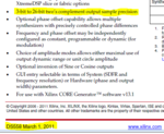
The output being 2's complement is stated in the documentation for the DDS core (on the first page too!):
Capture.PNG

Try reading the documentation for a core before using it, saves having to ask questions like this.
 

Aw darn! Mrfibble, now you've ruined the OP's learning opportunity to actually look at how the data results in strange outputs like that.
Sorry. And I know how you feel. ;)

Seriously it took me 1 second to recognize what was wrong with the data. I've seen this happen with DAC interfaces that had incorrectly defined settings or an incorrectly implemented FW driver.
No kidding, it's totally autopilot. See that sort of wraparound ==> doh, signed vs unsigned mixup.

But at least he still has a learning opportunity regarding reading the fine manual for IP cores. ;)

@Christian Chetcuti:
In xilinx core generator you have a "Datasheet" button (or similar, I forgot the exact label) that will open the PDF documentation for the core you are working on.

Relevant linkie: https://www.xilinx.com/support/documentation/ip_documentation/dds_ds558.pdf
 

managed to obtain correct output.. thanks a lot for your help, just 1 other question, I tried to multiply the output of the 2 sine waves generated but the output obtained was nothing near that accepted, (am output), the 2 sine waves designed were 2 khz and 100khz
 

You'll of course need a signed multiplier. So first do the multiplication of the two signed sines, and only after that do you do the signed to unsigned conversion as suggested earlier. And the multiplier needs to have appropriate input/output bit widths.
 
Status
Not open for further replies.

Part and Inventory Search

Welcome to EDABoard.com

Sponsor

Back
Top