trapoe
Member level 3
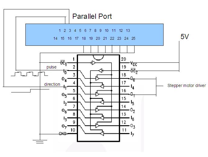
stepper motor using parallel port
Don't worry about exact output voltage, if you change pc it can change quite a lot. If you use a TTL compatible input it will work for Vinput > 2.6 V.
My question was about voltage required for motor winding, I don't find any electrical characteristic.
Sinisa from which part of Canada come the wonderful landscape you show ?
")