Vermes
Advanced Member level 4
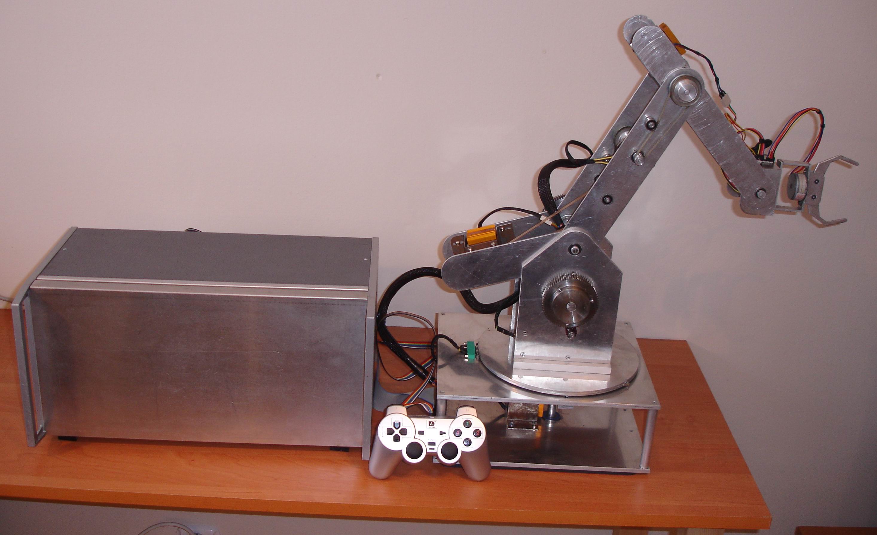
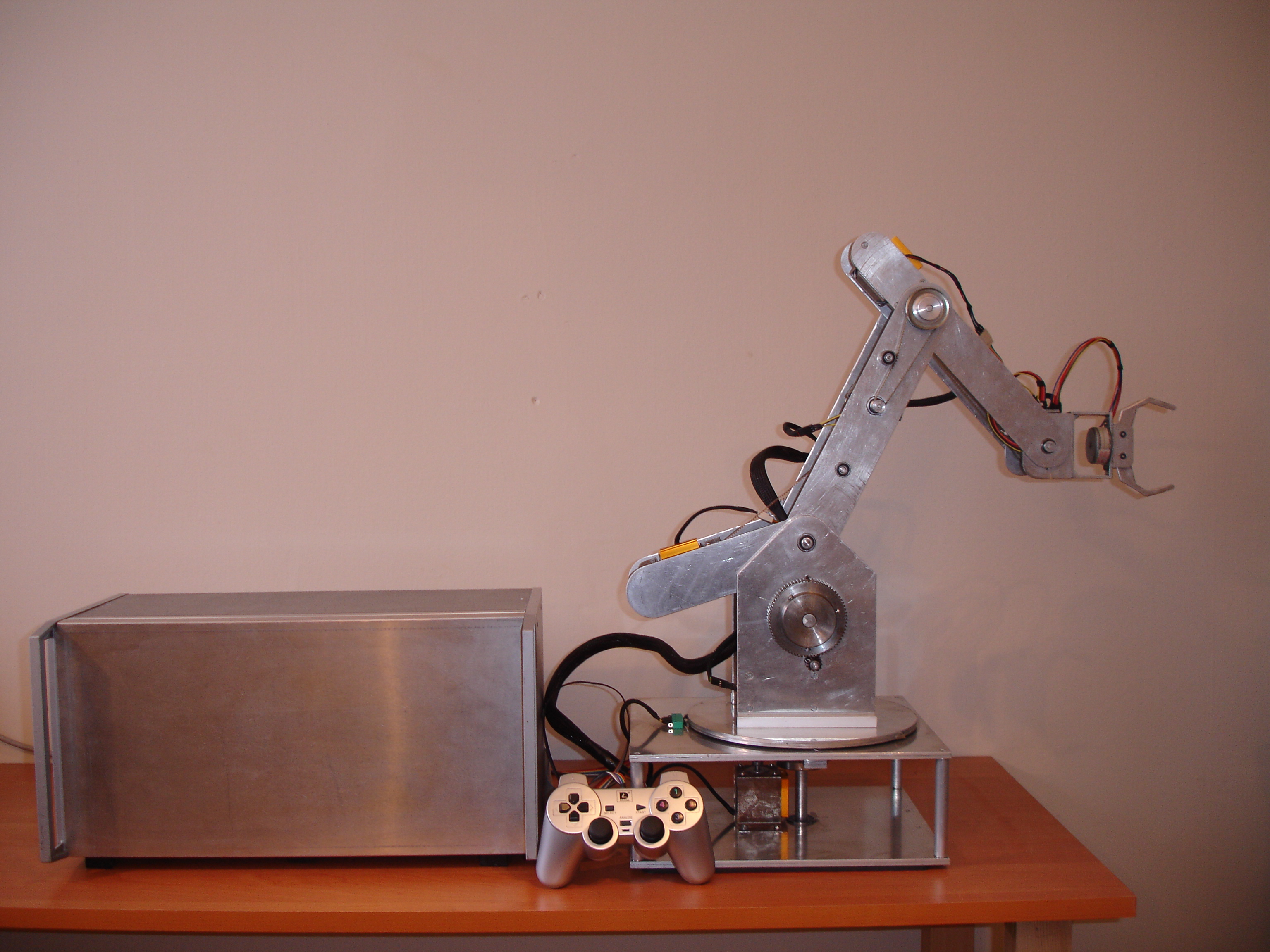
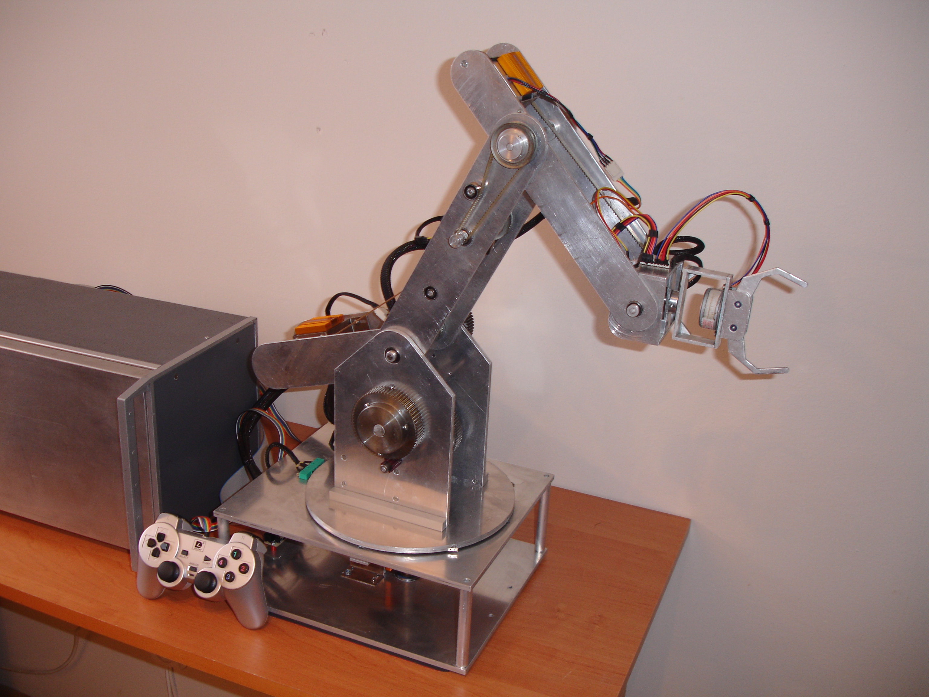
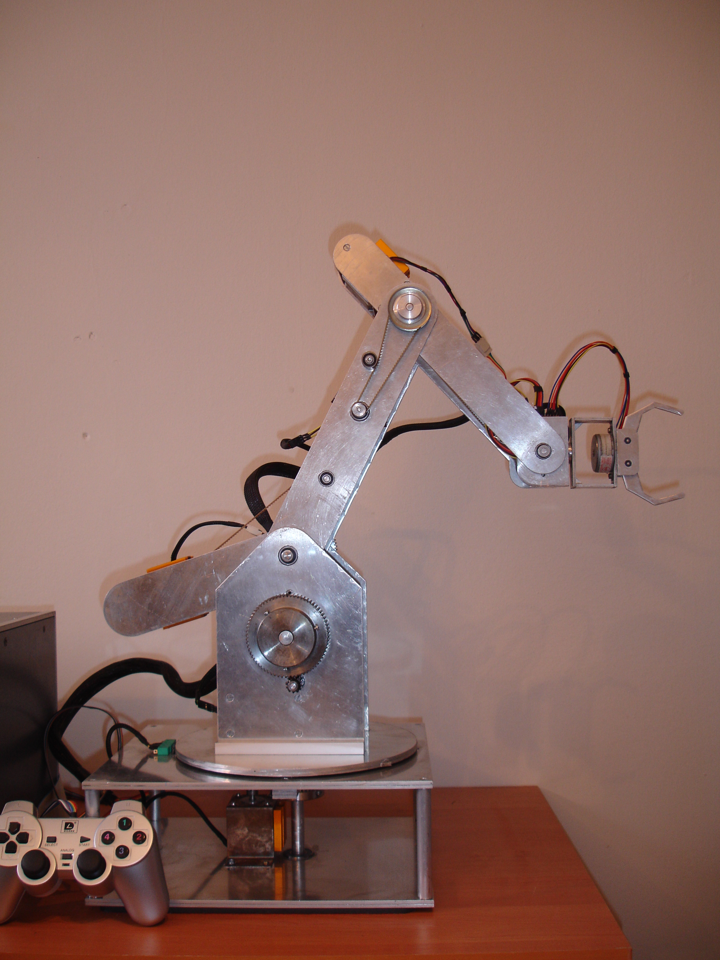
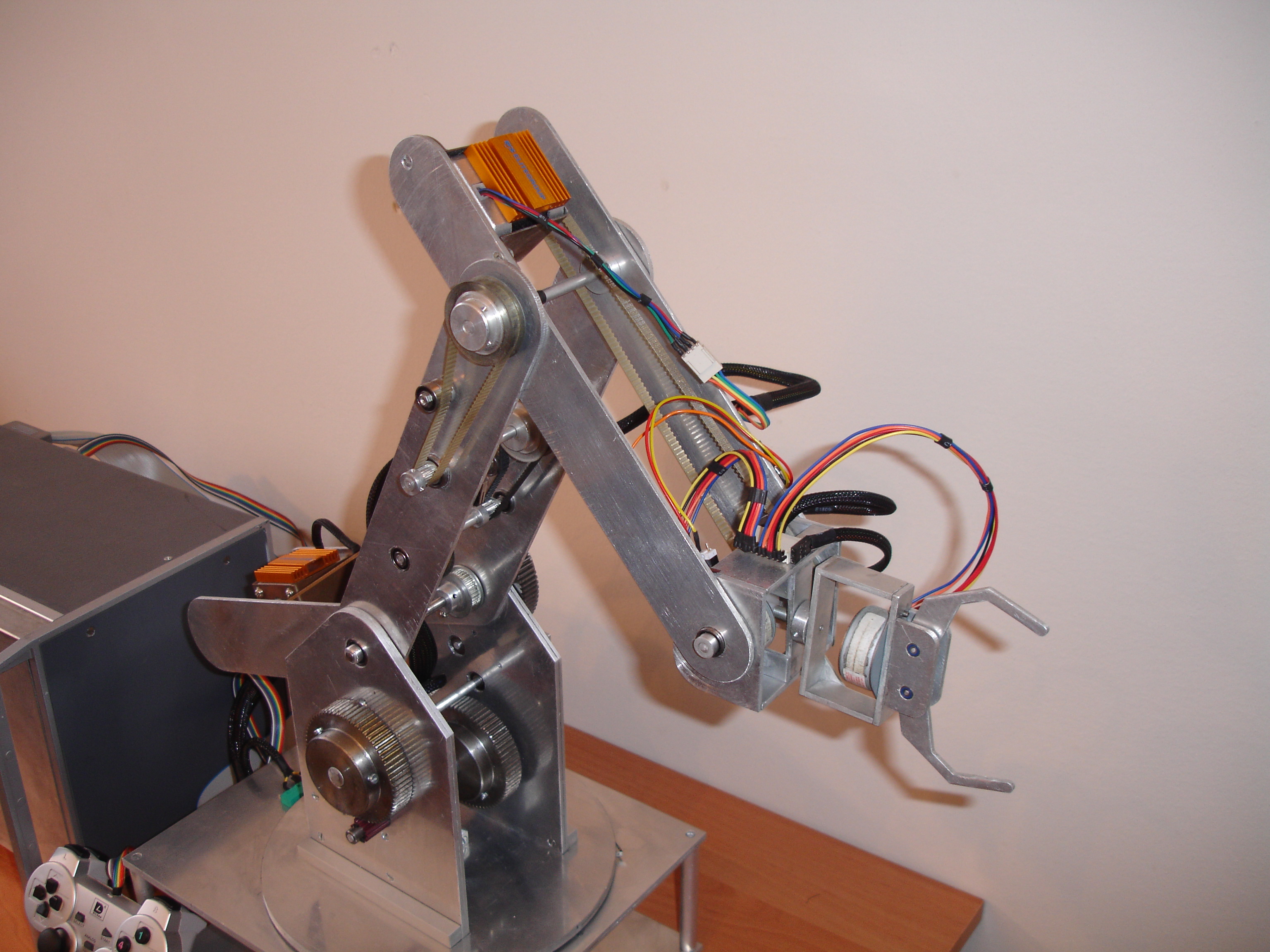
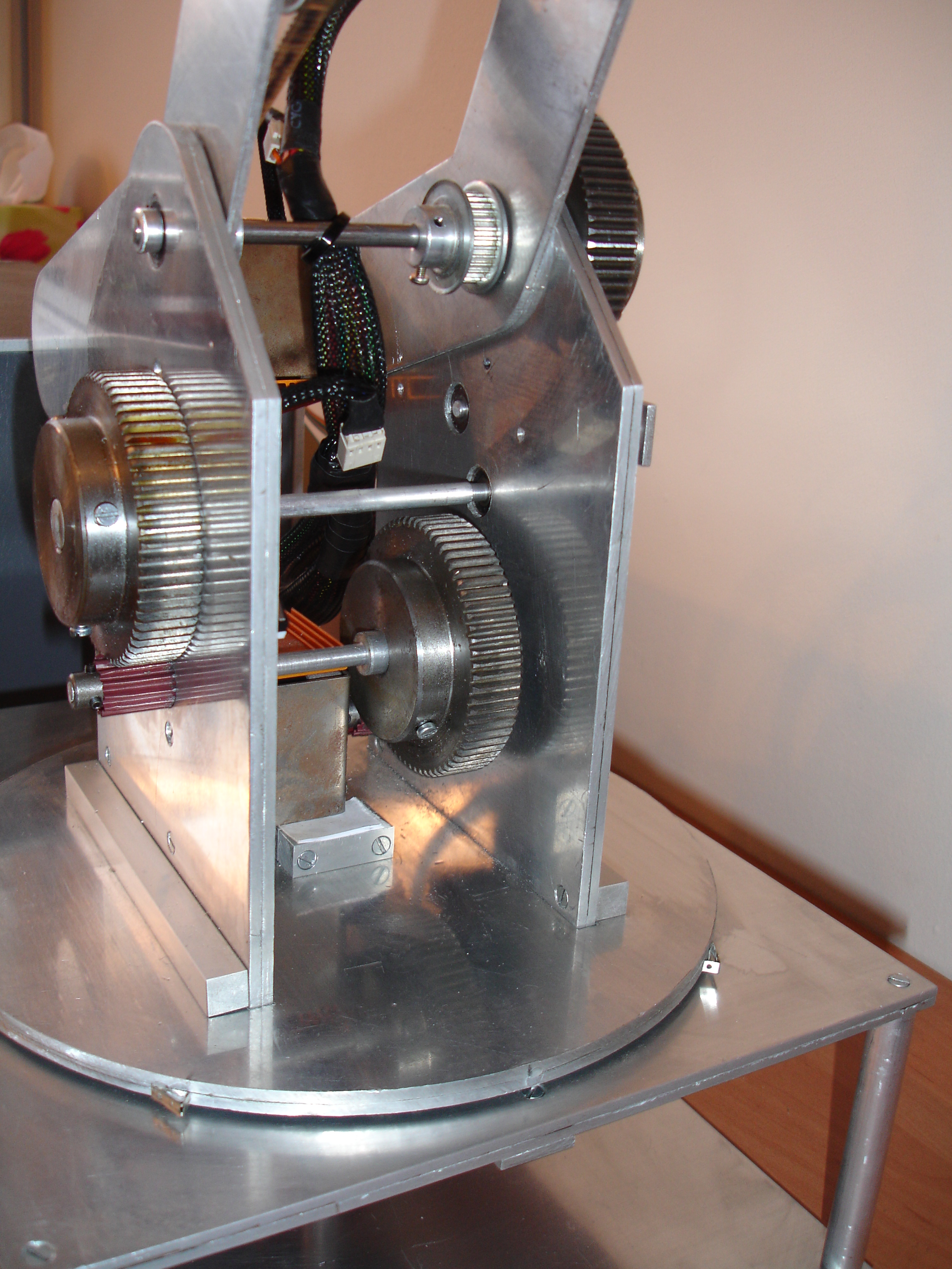
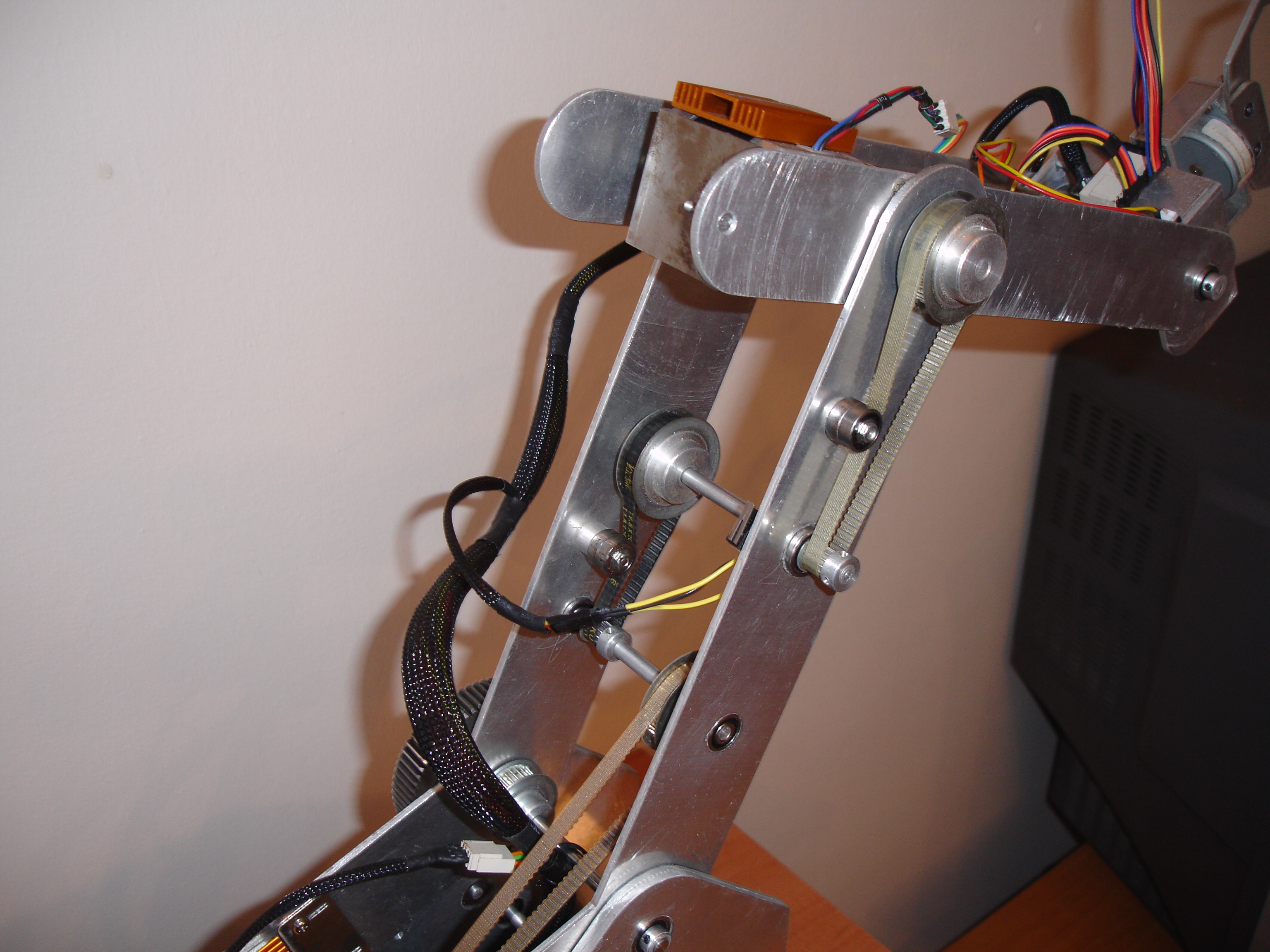
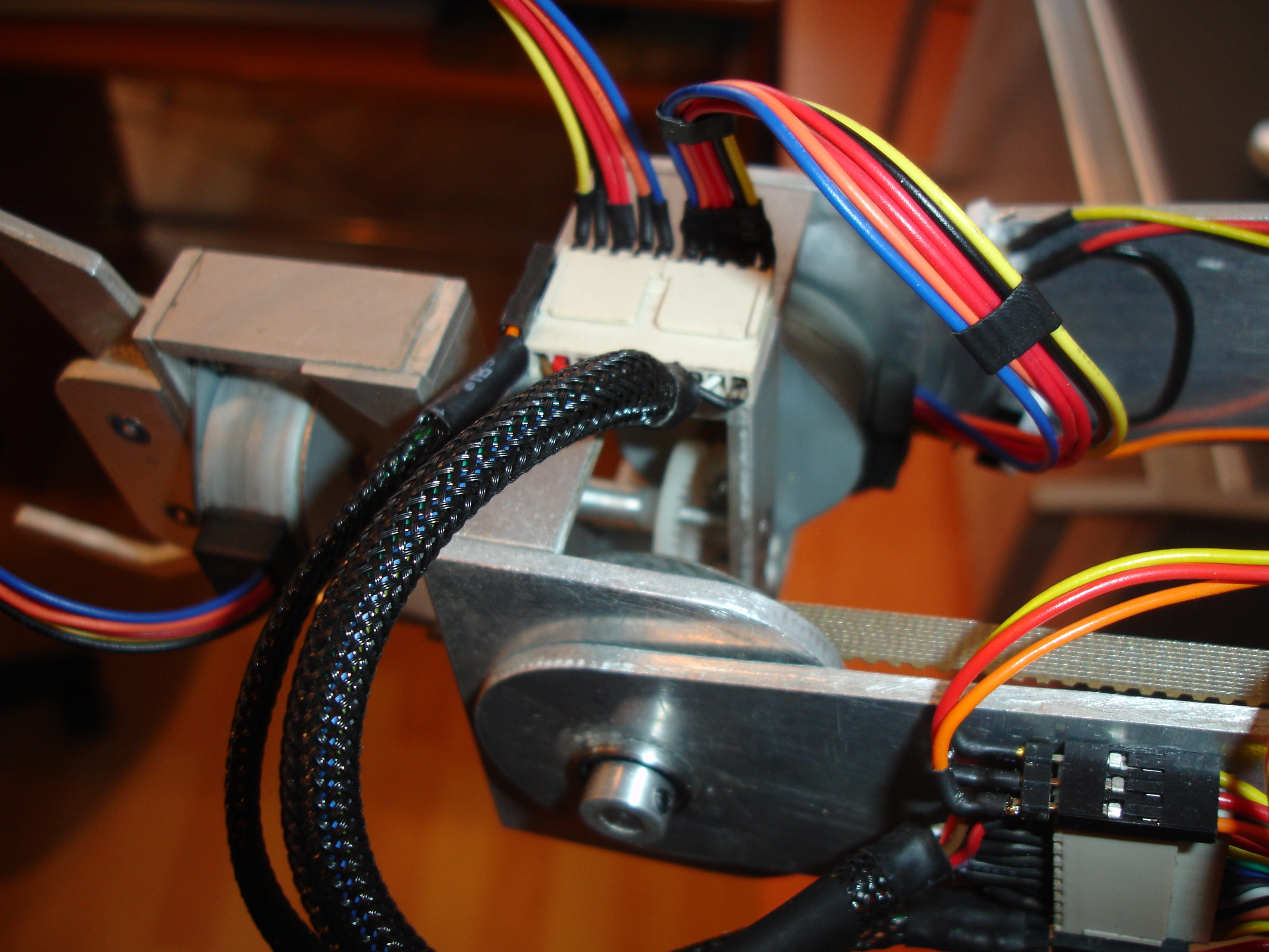
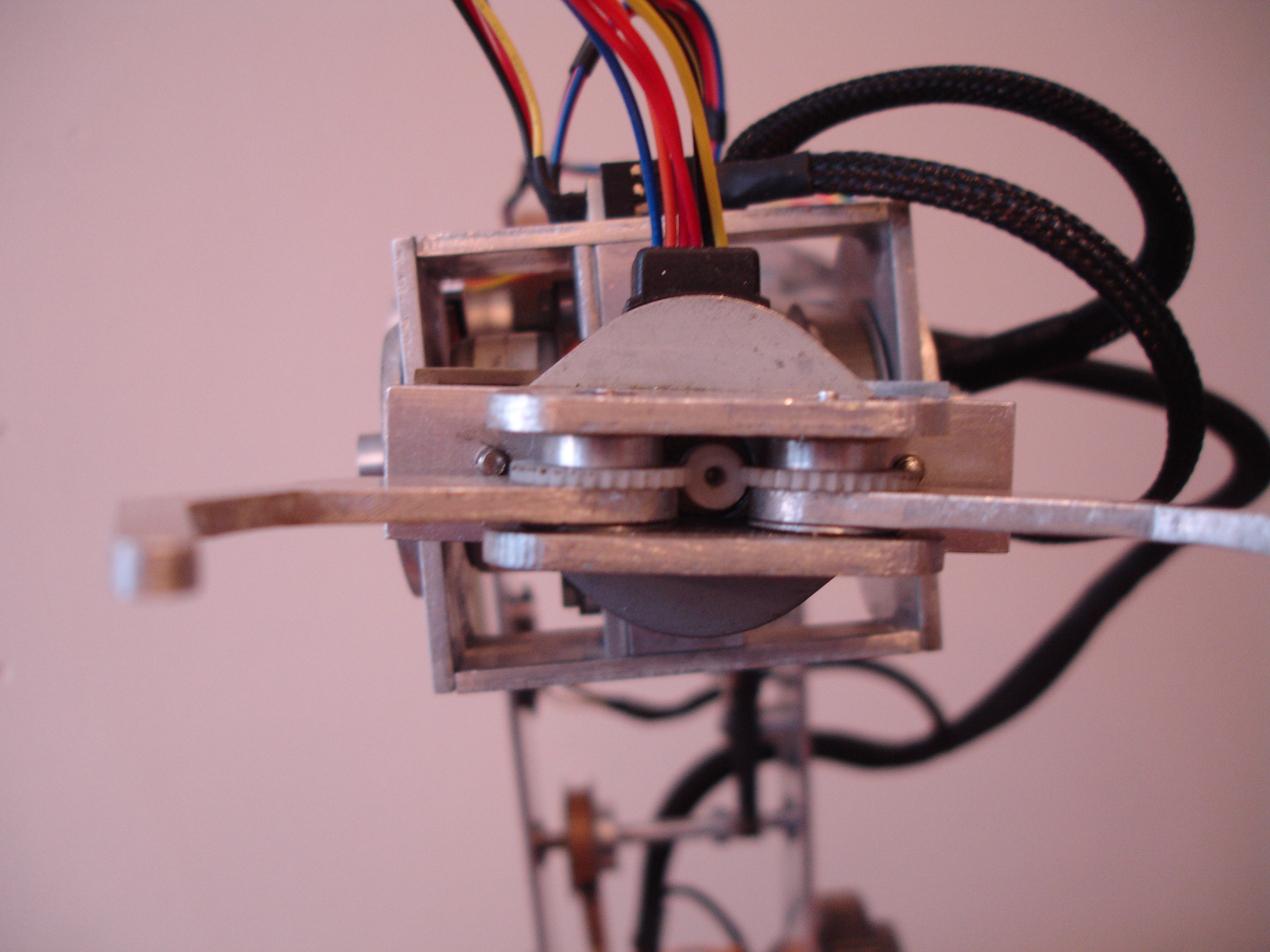
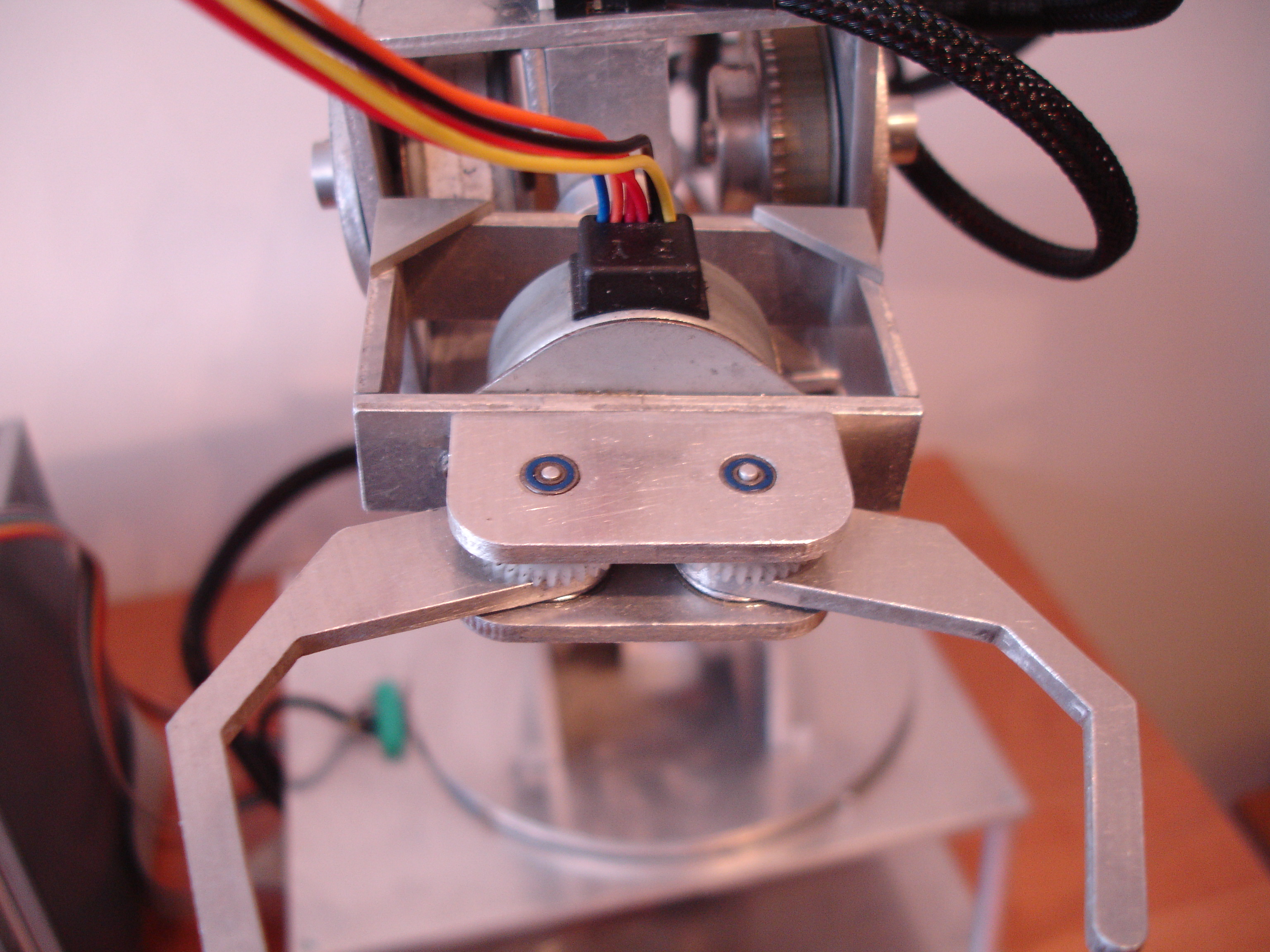
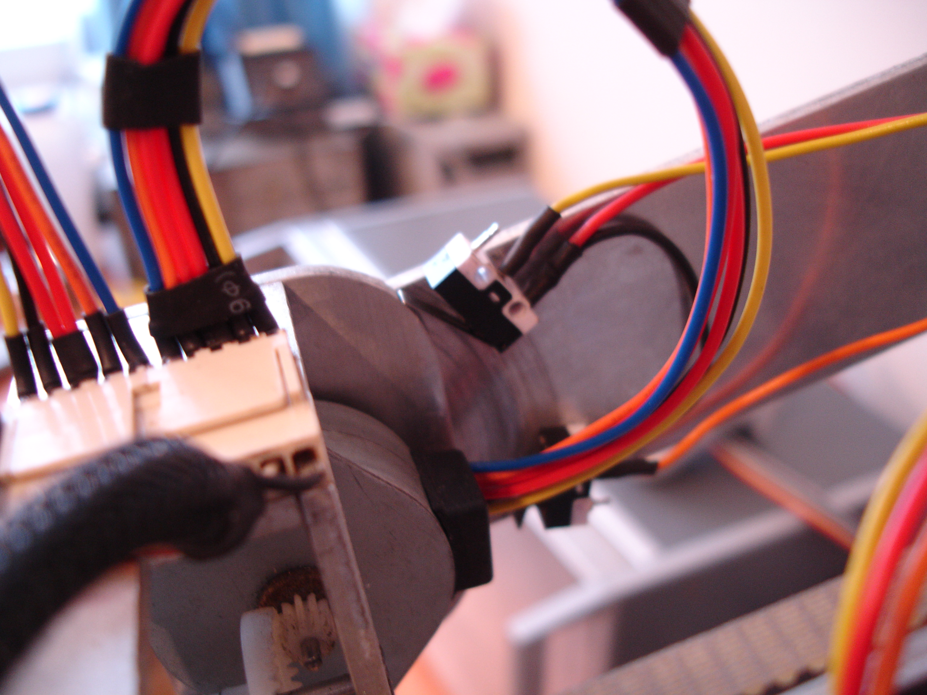
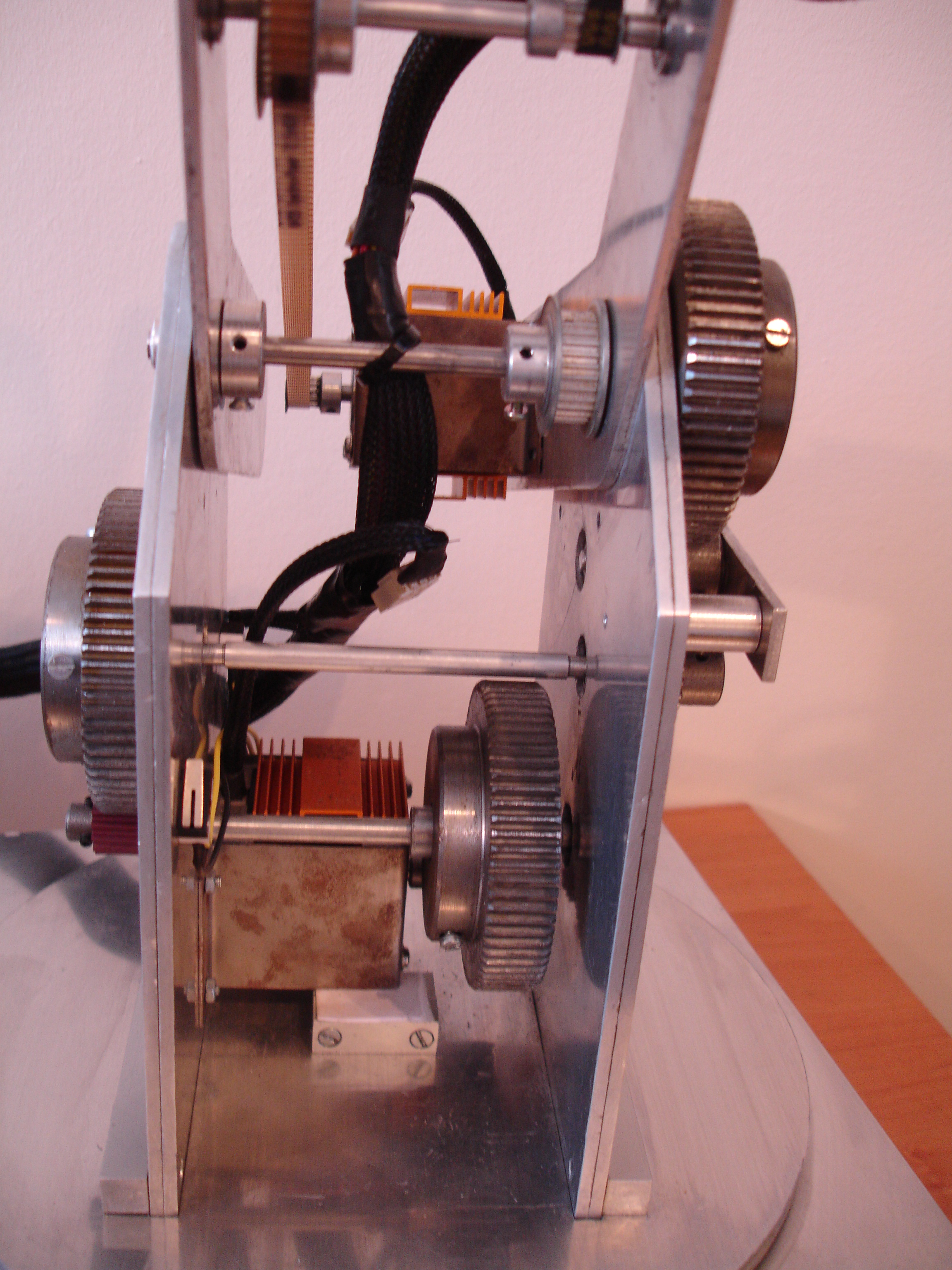
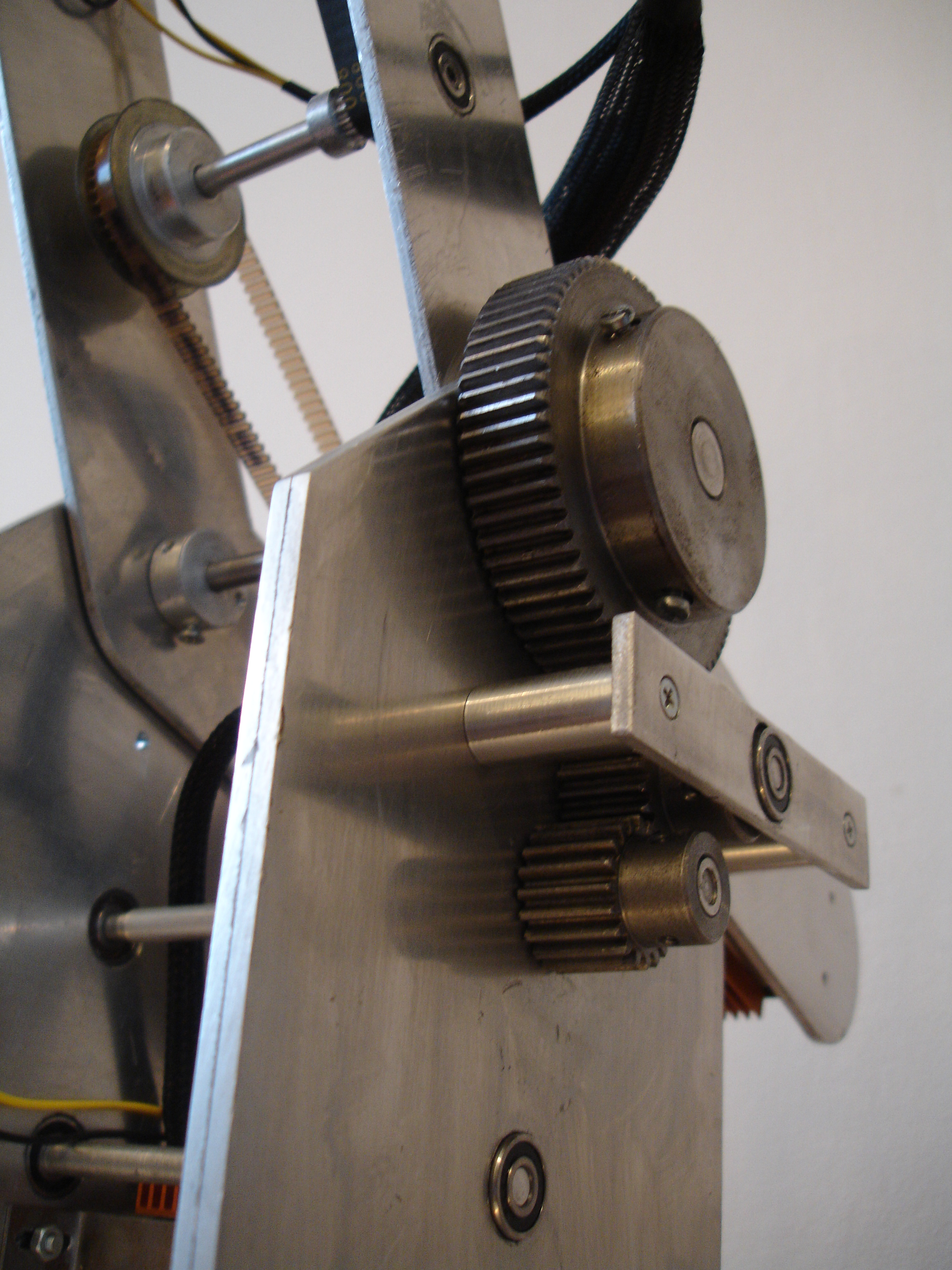
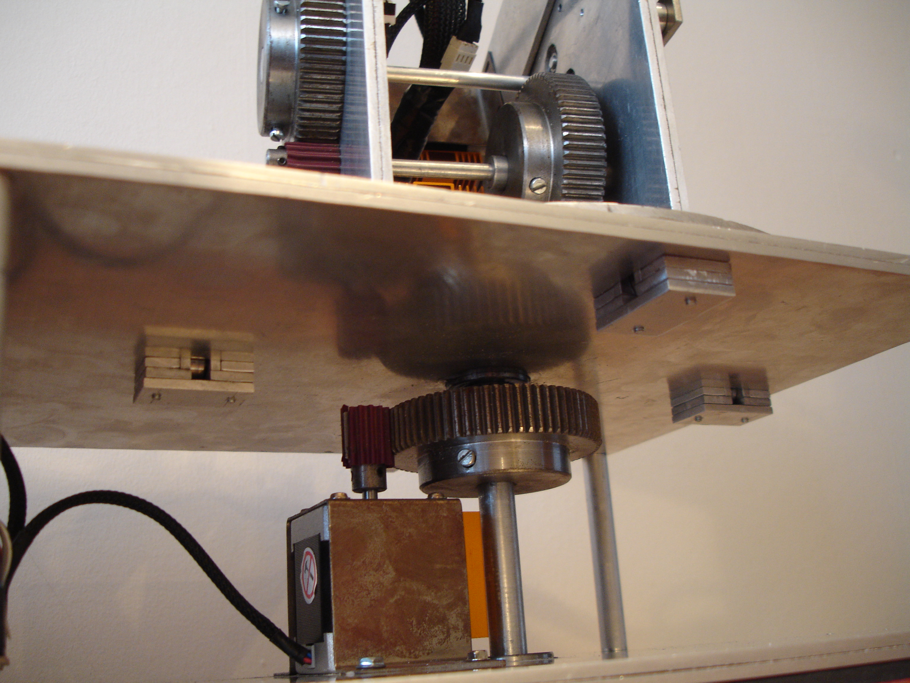
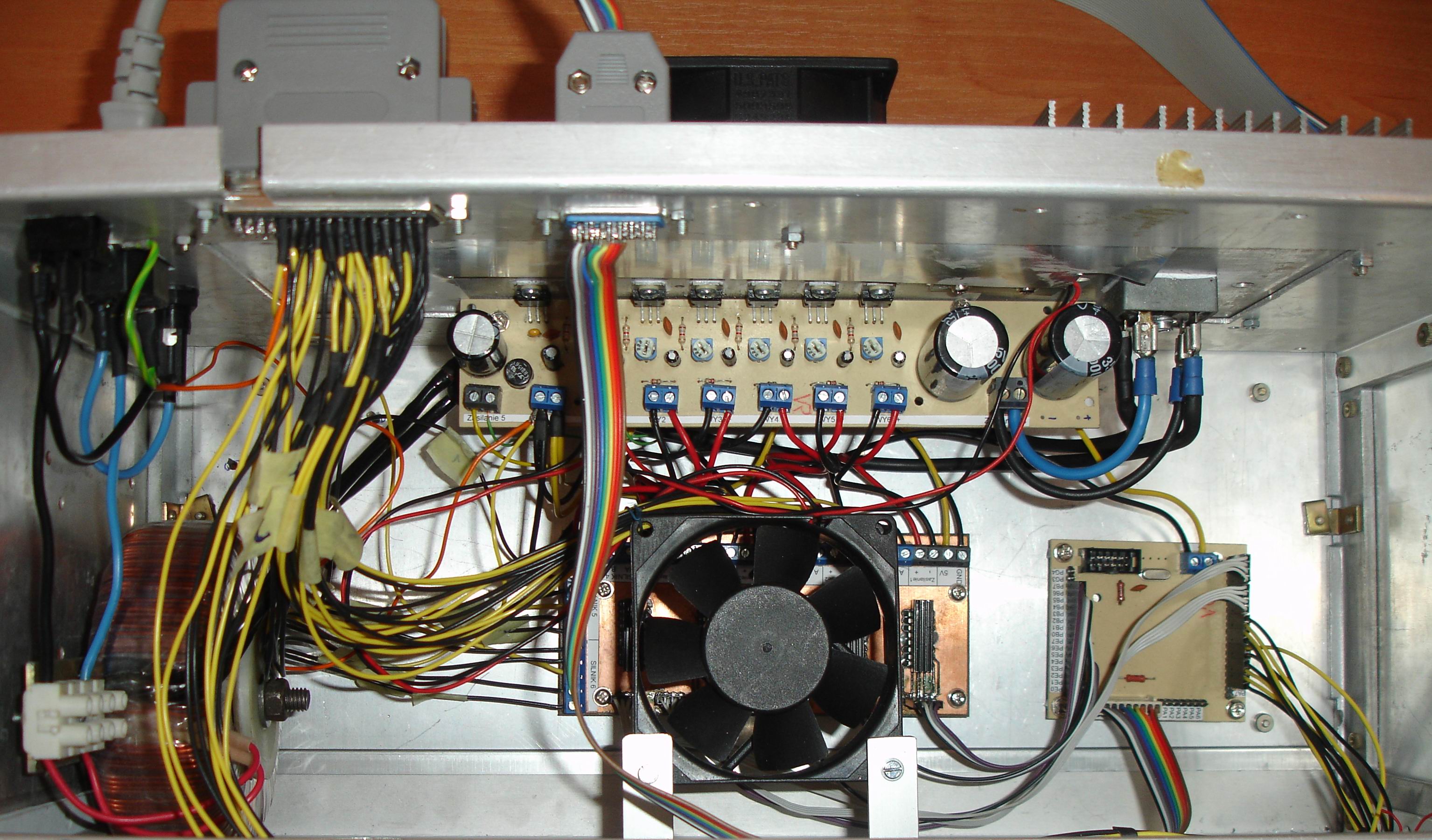
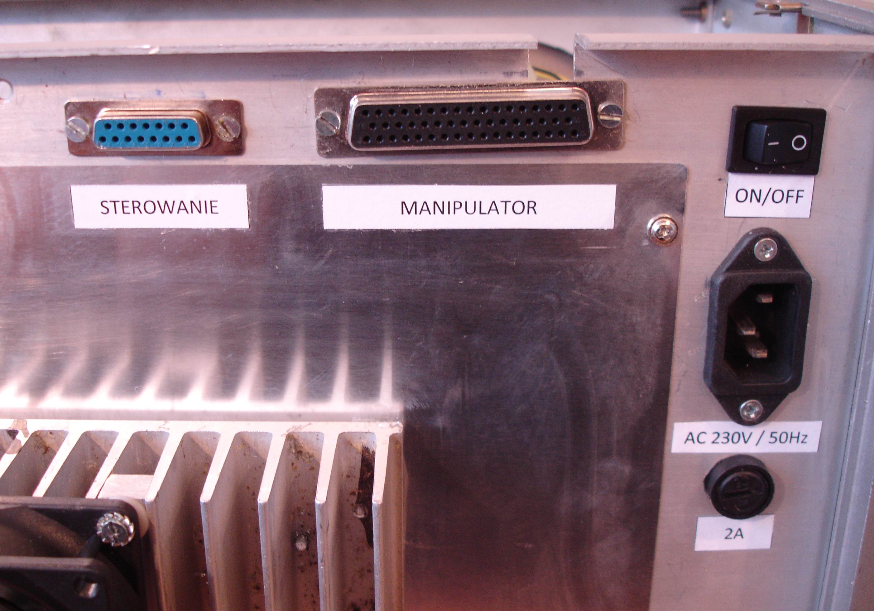
The arm of the robot was made of aluminum, except one of the drive axes made of a steel rod. Unipolar and bipolar stepper motors were used to move the arm. Power transmission is via steel and aluminum gears and gear belts cooperating with them. All axes have bearings on both sides. ULN2803 (for unipolar motors) and L293D (for bipolar) control the motors. Both systems are controlled directly by Atmega128 processor. Limit sensors restraining arm are also connected to the processor. The whole is powered from toroidal transformer 230V/18V. Also a power supply with 6 independent output steps of 12-24V (1,5A) and 5V (1A) power supply for processor and logic circuits was mounted. The whole is controlled by pad for computer games.
Video:
Photos:
Link to original thread (useful attachment) – Sterowane ramię robota [Qbot]