gauravkothari23
Advanced Member level 2
Hi All.
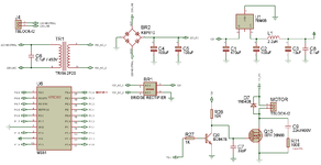
I have designed a circuit to control a DC Motor using PWM and 8051 controller. (Circuit attached).
Motor Specifications
Voltage: 240V DC
Watts: 560 Watts
RPM: 2900 RPM
In the circuit i am using a mosfet to drive the motor ON and OFF and controlling the speed of the motor using PWM at the constant speed of Approx 2900 RPM. Where C7, C9 and R31 was not connected Initially.
Will Also explain the working of the motor. A Round flange is connected to the motor Shaft with approx dia of 200mm and 10mm thickness. rotates constantly at the speed of approx 2900 RPM.
It has a manual braking mechanism which is not electronically controlled, where after every 8 to 10 seconds a brake is applied to the motor for approx 50 to 70 mSec. due to which the RPM drops to around 2500, which is acceptable. and again it takes 2 to 3 seconds for the motor to reach 2900 RPM and again after next 8 to 10 seconds again a brake is applied and the cycle continues to around 14 to 15 hours depending upon the requirement.
Now the Brake applied are not so smooth, but it has a sudden braking system which is applied for 50 to 70 mSec. and at the same time the circuit is also feeding the motor to operate at 2900 RPM Continuously, which is not being stopped at the time when brakes are applied.
Initially my problem was, as soon as i turn on the mosfet to start the motor, 5 out of 10 times the mosfet use to get shorted and was not able to control anymore. so later i added 33pF capacitor (C7) to the Gate and GND of the mosfet to avoid inrush current through the mosfet, which solved my problem.
But recently i started facing a new problem that after every 4 to 5 hours of continues operation of motor, the mosfet DRAIN-SOURCE pin or GATE-DRAIN-SOURCE pin gets shorted. have also tested the temperature which was around 70 to 75 degree celsius,
so i added a snubber C9 and R31 across the mosfet. but still the problem with the mosfet continues, it gets shorted within 4 to 5 hours of operation. but the temperature of the mosfet and snubber was around 100 to 110 degree celsius, within 10 to 15 minutes of operation.
can anybody please let me know, what the problem is, why the mosfet gets shorted again and again.