Continue to Site

Welcome to EDAboard.com

Welcome to our site! EDAboard.com is an international Electronics Discussion Forum focused on EDA software, circuits, schematics, books, theory, papers, asic, pld, 8051, DSP, Network, RF, Analog Design, PCB, Service Manuals... and a whole lot more! To participate you need to register. Registration is free. Click here to register now.

condenser and electret mics

Status
Not open for further replies.
hi
i got your reply audioguru
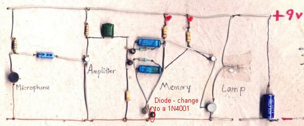
the diode polarities are all correct
and the + of the two 10 uf caps are connected to the collectors of both transistors too
but like i said from the beginning
after i connected the things exactly like the curcuit
i can clap to turn it on and then it turns itself off in about 31 seconds( i cannot turn it off by clapping)
and when it is off i can clap to turn it on again but then it turns itself off in about 31 seconds
the same goes on in this fashion

according to what it says on the site
the advice is like we clap to turn on the lamp and clap to turn it off

the result shows something totally diff
obviously something wrong with the curcuit
the bistable circuit cannot change states

regards
 

hi

audioguru
yes i even checked the transistors bc547 and bc337 pinouts
both t92 type
flat side facing us
from left to right
collector base and emitter
i also measured the 9v battery voltage it is above 8 v dc
regards
 

hi
thx for your reply audiguru
i do not have extra caps here
i will get some and check all connections once again and report to you later
thanks again
regards
 

You might have bought schottky diodes in place of the 1N4148 specified. Or the place you bought them from might have supplied them instead. For most applications, this does not matter much.

However, this bistable circuit uses the 1N4148 in the emitter of one of the transistors in order to compensate for the additional voltage drop due to the Vbe of the BC337 at the other.

Try changing that diode. Buy a 1N4001 and stick it in place of that diode and see how it works out.

The original circuit works as a monostable if that diode in the emitter is omitted.

2_1219126687.jpg
 

The "amplifier" transistor in the photo does not have a base bias resistor.
But then the original circuit doesn't either because the value of 4.7M is much too high.
 

hi guys
so the base resistor of the amp is too high
hmmmmmmm
and i need to change the in4148
hmmmmmmmmm
:)
i feel like i will have to change many things now
hold on anything
i am gonna try all these now
since i got the in4001 and some new caps


regards

Added after 32 minutes:

hi guys
i finally made it work
reporting:)
i changed some parts
the amp input 10uf i changed it to a new 10uf cap i bought today
i changed the amp 4.7M to 47k(aduioguru said this value is too high so i changed it to 47 k and tried and it worked)
i also changed the bc547 emitter diode in4148 to in 4001
and i also changed that 100nf to 10 nf( the clap switch is now not as sensitive as it was the first time it was too sensitive but now it is better)
all working fine now
thanks for all replies and teaching
regards
 

the value of 4.7M is much too high
Not necessarily. You can imagine the transistor stage also as prebiased switch. It don't need to amplify the input signal undistorted. So I think, the circuit is O.K, if the sensitivity is sufficiant. Your right of course regarding the wallpaper circuit.
 

With a 4.7M base resistor, the transistor is cutoff.
If a clap makes a negative-going signal then the transistor "amplifier" won't do anything.
 

Audioguru said:
The "amplifier" transistor in the photo does not have a base bias resistor.
But then the original circuit doesn't either because the value of 4.7M is much too high.

<Galileo> But it works!</>

For each clap, the microphone produces a decaying oscillatory waveform. If the transistor is in cutoff, it will be driven ON. If it is in saturation, it will get driven OFF. If it is in the active region, it will be driven between ON and OFF. With a sufficiently loud clap, of course.

Without a bias resistor, the leakage of the (electrolytic) coupling capacitor biases the transistor at the threshold of conduction. This particular circuit will work with a wide range of values for that bias resistor, or no bias resistor at all.

It will not, however, work with a low leakage input capacitor and NO bias resistor.
 

Re: clap switsh

hi
can i use condenser mic
that have three leeds out???
:cry:

Added after 27 minutes:

ahmm
i use adaptor to my clap switch and it is working..
but after 3 minuits energizing the L.E.D turns off..
it is necessary to use battery???
 

Re: clap switsh

hi all, the mics can detect any sound from environment. How to make it to just detect the hand clapping sound? I noticed that the circuit provided by him can detect any sound from environment right? If so, this cannot be called as clap switch lolx?

---------- Post added at 18:15 ---------- Previous post was at 18:14 ----------

This is the link to the circuit.
**broken link removed**
 

There is nothing in that extremely simple circuit to "filter" sounds. Barking by a dog, hammering nails by a wood worker or gun shots all cause the same output as clapping.

What makes hand claps sound different from any other loud abrupt sound? How would you filter out all other sounds but allow only hand claps?
 

i also don't know how to make it, i tried to consult many people, none of them can do that, i'm currently doing my final year project on sound recognition desktop fan, my lecturer insist to have only hand clapping sound to trigger the fan to start. I tried to design out bandpass filter but it didn't work.He suggested me to do some frequency sampling and ask me to find out myself. But i have no idea on doing this. This is the thread that i asked before in this forum and there were some advices given by others. The suggestions also seems hard for me to understand.:sad:
https://www.edaboard.com/threads/193494/#post810387
 

Why are you making that extremely simple circuit for "a final year project"? The circuit is designed for little kids to make.
Did you study about "sound recognition?

Don't you think it is your brain that remembers the sound produced by hand claps then recognises it when it is heard again?
Use a computer and complicated software to replace your brain.

Maybe your lecturer wants you to simply filter out low frequency sounds so that only loud, abrupt high frequency sounds trigger the simple circuit. But then many other loud, abrupt high frequency sounds will also trigger it.
 

The suggestions also seems hard for me to understand.
The suggestions are basically simple and most likely insufficient for a selective detection, as addressed by Audioguru. You have to specify the intended grade of selectivity for your project. If you imagine similar percussive sounds like hammer blows, clapsticks, hail on a tin roof, popcorn making, marbles clicking, which can be sorted out?
 

sorry for asking stupid question, i know it's easy for you, but it might be difficult for me as a beginner. So in order to filter out low frequency, i should design a high pass filter?
 

So in order to filter out low frequency, i should design a high pass filter?
Can be a starting point I think. I suggest. that you start to evaluate the characteristics of hand clapping and other percussive sounds. All you need is a computer with a souncard, a microphone and some sound recording and processing software. I used CoolEdit at times, but there are much other powerful products, also good ones in the public domain. The software can record sounds, display the waveform in time domain and it's frequency spectra, perform filtering and dynamic processing.
 

So in order to filter out low frequency, i should design a high pass filter?
The extremely simple circuit already has a highpass filter as explained in its article: "The output of the (transistor) amplifier is converted to a sharp pulse by passing it through a (relatively) low valued capacitor, of 0.1 microfarads (100 nanofarads)".
But millions of ordinary things produce "loud, abrupt high frequency sounds". The extremely simple circuit is missing "sound recognition".
 

hi all, i'm working on a project call sound recognition desktop fan. These are the circuits that i designed out. The 1st circuit is having higher sensitivity, which means it can detect any sound from the environment, but my project is to use hand clapping sound to trigger the fan to on. So i designed out another circuit to lower the sensitivity and it works. Can anyone please explain to me the theories behind these 2 circuits? Is there any theory or calculation that can explain the changes that i made in these 2 circuits? I have circled out the changes that i made.
https://obrazki.elektroda.pl/89_1293083812.jpg (higher sensitivity circuit)
https://obrazki.elektroda.pl/85_1293084480.jpg (lower sensitivity circuit)
 

Status
Not open for further replies.

Part and Inventory Search

Welcome to EDABoard.com

Sponsor

Back
Top