Continue to Site

Welcome to EDAboard.com

Welcome to our site! EDAboard.com is an international Electronics Discussion Forum focused on EDA software, circuits, schematics, books, theory, papers, asic, pld, 8051, DSP, Network, RF, Analog Design, PCB, Service Manuals... and a whole lot more! To participate you need to register. Registration is free. Click here to register now.

Commonmode Voltage range for Differential Amplifier

Status
Not open for further replies.

txbob

Junior Member level 2
Joined
Nov 24, 2008
Messages
23
Helped
0
Reputation
0
Reaction score
0
Trophy points
1,281
Activity points
1,462
Hi,
I have a question on differential mode application
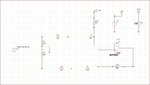
In diff amp application as in enclosed picture will you please tell me how what will be the Common mode voltage (+/-) seen by the op amp.
The applied voltage is 36v 60Hz peak. With respect to op amp gnd(0v) where I will measure this(you can use ref desc)
Thanks
 

Attachments

  • dIFF-AMP.JPG
    dIFF-AMP.JPG
    221.8 KB · Views: 114
Last edited:

The term "ideal OP" seems misplaced if you are asking for the input voltage range with a specific supply voltage. Perhaps we should assume a typical "IO RR" (input/output rail-to-rail) amplifier

To achieve a bipolar differential input range with single supply, the reference voltage must be Vcc/2 rather than Vcc.
 
  • Like
Reactions: txbob

    txbob

    Points: 2
    Helpful Answer Positive Rating
Fvm,
Thank you
Error in vcc voltage corrected. Op amp name corrected
My question is, In this set up what is the common mode voltage seen by the op amp
If I use a scope to measure this common volatge where I will measure it (indicate the refdesc or drawing helpful)with respect to ground.
Please help me with this squestion
 

The common-mode voltage is the DC voltage seem by both inputs at the same instant as measured to ground. You can calculate that from the values shown on the schematic. Since the source is only an AC signal with no DC it does not contribute to the common-mode voltage and can be replaced by a short (since an ideal source has zero resistance).

I take it this is homework so you need to show some work in solving this problem.
 

The common-mode voltage is the DC voltage seem by both inputs at the same instant as measured to ground. You can calculate that from the values shown on the schematic. Since the source is only an AC signal with no DC it does not contribute to the common-mode voltage and can be replaced by a short (since an ideal source has zero resistance).
Not exactly. The simple differential amplifier has an asymmetrical input impedance, thus part of the floating differential AC voltage will be converted to common mode voltage. You can calculate all circuit node voltages for minimum (-36V) and maximum (+36V) input voltage to get the utilized amplifier common mode range. In this calculation, ideal OP parameters should be assumed (inifinite gain, zero input current).

I take it this is homework so you need to show some work in solving this problem.
Yes, absolutely.
 

Hi,

The common-mode voltage is the DC voltage seem by both inputs..

If you want to know this DC voltage, then calculate as if your DC source is short circuit. (to confirm your calculations: my result is 2.4221V)

Including your AC input the common mode input will swing around this DC voltage. (my result: 2.4221 +/- 0.9952V)

hope my calculations are correct.


Klaus
 

Status
Not open for further replies.

Similar threads

Part and Inventory Search

Welcome to EDABoard.com

Sponsor

Back
Top