Vermes
Advanced Member level 4
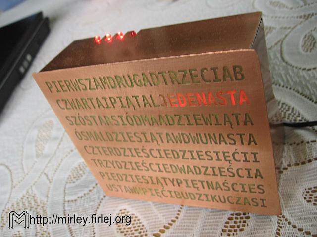
It is a simple clock working in 24-hour cycle, except that the same presentation time is 12-hour. Unusual is the method of presentation the time. Hours and minutes are highlighted on a special panel with appropriately spaced LEDs (65 units). For example, 12:35 is represented by the words “Twelfth”, “Thirty” and “Five”. The main panel shows the time with precision of 5 minutes, while additional 4 LEDs increase the precision of indications of 1 minute.
Using the clock may initially seem difficult, but it is easy to get used to it. The system is equipped with a loud alarm and battery time back-up in case of power failure. The device is closed in a housing made of polished pieces of laminate covered with clear varnish. A popular system PCF8583 is used for the countdown and the whole device is based on the microcontroller Atmega16. The clock takes about 100mA current at 5V power supply, during normal operation.
Scheme:
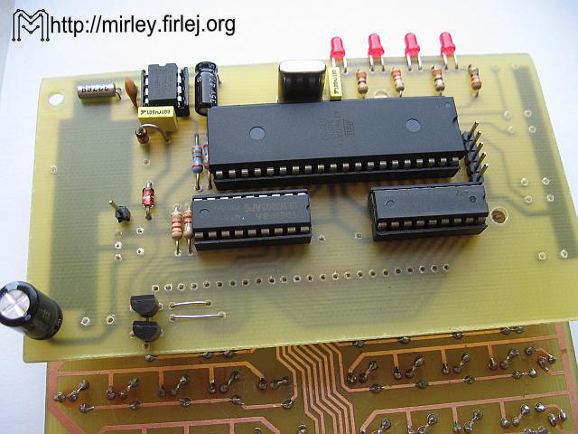
The main element of the system is U1 (Atmega16) with a quartz resonator X1 (16MHz) and capacitors C1 (22pF) and C2 (22pF). Switches S1-S3 (uSwitch 12x12mm) are the keypad of the clock, allow you to set the time and the alarm. LEDs DL1-DL4 are the secondary display for minutes counter. Prog connector (header) is used to program the processor. The real-time clock U2 (PCF8583) is responsible for timing in the system. Crystal oscillator X2 (32,768kHz) and capacitor C8 (33pF) are required for its proper operation. Additional capacitors C6 (100nF) and C7 (47uF) provide the voltage filtration in the system U2. After a power failure, the timing is supported by battery BAT1 (3V) and uninterruptible power supply with LED D1 (1N4148) and D2 (1N4148). Resistors R3 (3,3k) and R4 (3,3k) allow the proper operation of the I2C bus, and thus the correct time read and write from/to the system U2. The display is divided into two segments multiplex-controlled by transistors T1 (BC327) and T2 (BC327). Resistors R1 (3,3k) and R2 (3,3k) limit the current of those transistors bases. The cathodes of diodes in the segments of the displays are controlled via the buffer inverters U4 (ULN2803) and U5 (ULN2803), like the piezo indicator with generator BUZ1 (5V). The display connector are the header GP1, GP2 and GP3 strips. Power is connected to the connector Z1 (ARK2) directly on the filtering capacitor C3 (220uF) and the stabilizer system U3 (7805). Capacitors C5 (100nF) and C4 (100uF) filter the supply voltage.
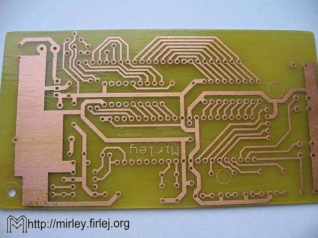
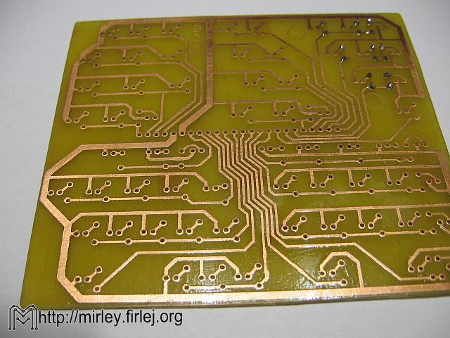
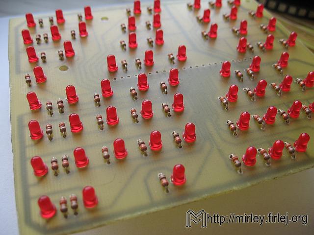
The display of the clock is quite simple. Resistors R1-R65 (220R-330R selected depending on the diode) limit the LED's D1-D65 current. LEDs are divided into two sections, the first are elements of D1-D30, and the second are diodes D31-D65. Contact with the controller pad is provided by PIN headers GP1, GP2 and GP3.
Photos:
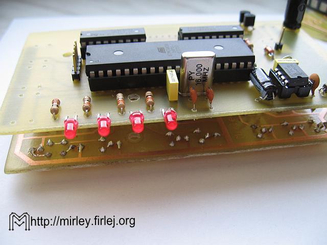
A big problem may be the mechanical design of the clock, because it is not easy to make and requires a bit of patience. Most important is the front panel, made of a this one-sided laminate (the thinner the better, 0,5mm or 0,8mm would be good). Print to press must be perfect because every over-etching after lighting LEDs will be then seen. The front panel can be done little bigger than the one proposed in the drawing, gluing plate edges with adhesive tape to protect them against over-etching. Always it will be easier to grind the panel to the rest of the housing than make a new one, slightly larger.
The second step was to make the compartments on the back of the front panel using strips of laminate with a width of 1-1,5cm. Each inscription on the display is separated from the another by at least one “false” letter, which should not be illuminated, and allows you to paste two compartments and a better separation of one inscription from another. The easiest way is to draw the front panel from the back in which place there should be mounted strips of the laminate. Gluing can be done by using Super Glue or similar adhesive, remembering not to allow gaps between each compartments, and between the panel and the compartments. All gaps and deficiencies will result in one character lighting through another. While bonding, photographs at the bottom of the page will be some help. After sticking compartments, grind the front panel with fine sandpaper, and then paint with clear lacquer spray.
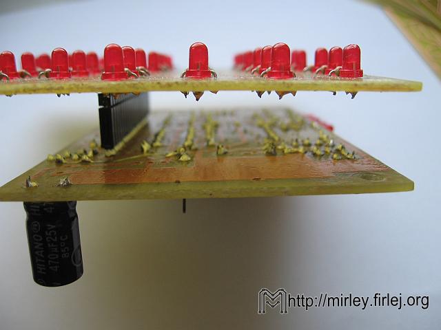
The driver board with the display board should be screwed with screws 3mm, otherwise after pressing the button, headers or drawer connector can break from the boards. If everything was well made, and the compartments correctly pasted, the display board should be applied straight to the front panel, and LEDs hide in the compartments. Depending on the length of the string, compartments have different lengths and different number of LEDs that backlight them. Mounting of the display board to the panel with strings can be performed in any way, such as drilling small holes 1mm in the board and moving pieces of wire previously soldered to the laminate in the compartments.
The sides and top of the housing should be also cut from the strips of laminate, grind and paint like the front panel. The back cover could be empty to make watching the construction of the clock available.
Link to original thread (useful attachment) – Zegar z wyświetlaczem tekstowym
Last edited: