Continue to Site

Welcome to EDAboard.com

Welcome to our site! EDAboard.com is an international Electronics Discussion Forum focused on EDA software, circuits, schematics, books, theory, papers, asic, pld, 8051, DSP, Network, RF, Analog Design, PCB, Service Manuals... and a whole lot more! To participate you need to register. Registration is free. Click here to register now.

Class A Transistor Amplifier Analysis

Status
Not open for further replies.

naspek

Member level 1
Joined
Feb 17, 2010
Messages
37
Helped
0
Reputation
0
Reaction score
0
Trophy points
1,286
Activity points
1,546
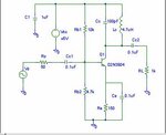
Hey there.. I've got couple of questions need to be answer.. i really got no idea to solve it..

1) During DC biasing measurement, if CE changes from 0.1 µF to 1 µF, what happen to the readings in VE (assume CE is ideal capacitor, no parasitic resistance or inductance)?
2) The input and output (VB and VL) waveform should be approximately 180° out of phase during resonance. VB is leading VL or in reverse way? Why?
 

Since I can only guess what you mean with VE, VB and VL it would be wise to use words instead of self-created abbreviations.
You have mentioned "resonance" - is there any LC combination around the transistor?
 
  • Like
Reactions: naspek

    naspek

    Points: 2
    Helpful Answer Positive Rating
Since I can only guess what you mean with VE, VB and VL it would be wise to use words instead of self-created abbreviations.
You have mentioned "resonance" - is there any LC combination around the transistor?

thank u for your reply sir.. the circuit is shown below.. really hope u can help..
a.jpg
 

At resonance, the tuned circuit is resistive, so if Vb increases, Ib increases so Ic increases, so Vc must decreases. So if Vb goes +ve, Vc goes -ve, 180 degrees phase shift.
Your first question "does Ce affect the DC bias" , it should not unless the amplifier is oscillating, changing Ce might stop it, change the frequency etc which could lead to shift in the transistors DC bias.
Frank
 
  • Like
Reactions: naspek

    naspek

    Points: 2
    Helpful Answer Positive Rating
At resonance, the tuned circuit is resistive, so if Vb increases, Ib increases so Ic increases, so Vc must decreases. So if Vb goes +ve, Vc goes -ve, 180 degrees phase shift.
Your first question "does Ce affect the DC bias" , it should not unless the amplifier is oscillating, changing Ce might stop it, change the frequency etc which could lead to shift in the transistors DC bias.
Frank

i think u didn't answer my question there..
During DC biasing measurement, if CE changes from 0.1 µF to 1 µF, what happen to the readings in VE
 

Hey there.. I've got couple of questions need to be answer.. i really got no idea to solve it..

1) During DC biasing measurement, if CE changes from 0.1 µF to 1 µF, what happen to the readings in VE (assume CE is ideal capacitor, no parasitic resistance or inductance)?
2) The input and output (VB and VL) waveform should be approximately 180° out of phase during resonance. VB is leading VL or in reverse way? Why?

to 1.) If VE is the dc voltage across RE (why don't you answer my question?) it does not depend on any CE change. However, the sinusoidal output amplitude will change due to change in signal feedback. Better: The gain of the stage is changing.

to 2.) In the frequency domain a phase shift of +180 deg is identical to a shift of -180 deg. Thus, you cannot discriminate between leading and lagging. In this case, it's helpful (and correct) to know that - in fact - the signal is inverted (rather than shifted in phase).
 
Last edited:
  • Like
Reactions: naspek

    naspek

    Points: 2
    Helpful Answer Positive Rating
to 1.) If VE is the dc voltage across RE (why don't you answer my question?) it does not depend on any CE change. However, the sinusoidal output amplitude will change due to change in signal feedback. Better: The gain of the stage is changing.

to 2.) In the frequency domain a phase shift of +180 deg is identical to a shift of -180 deg. Thus, you cannot discriminate between leading and lagging. In this case, it's helpful (and correct) to know that - in fact - the signal is inverted (rather than shifted in phase).

thank u for your help.. but..
both questions carry 20 marks.. so, is there anything more can be added?
 

Status
Not open for further replies.

Similar threads

Part and Inventory Search

Welcome to EDABoard.com

Sponsor

Back
Top