darunium
Newbie level 4
Hi All,
To caveat this I am no EE, sorry if my question is silly! Any help is really appreciated!
I am trying to probe a load with both a DC bias via one instrument and an AC bias via another (I've tried putting them in series in a variety of configurations, but that hasn't worked out because of the way that the internal electronics on the instruments connect to grounds).
The method I would like to imploy is two loops, one for DC current and one for AC current, but to isolate them from one another I'd add an inductor to the DC loop, and a capacitor to the AC loop.
My load is in the Mohm-Gohm range. My DC bias 10-800mV. My AC bias 2-10mV at 500-1500Hz.
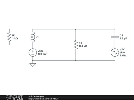
My question is: what qualities of the inductor and capacitor should I look for? Material? Maker? Parameters?
My understanding is that I would want a high inductance and high capacitance based on the idealized impedance formulae.
but in practice do I just want the highest L and C possible or should I be careful about that? To remind my load is in the 100kOhm-1Gohm region, so I want my capacitor to provide <1kOhm resistance to the 1kHz signal, and the inductor to provide <1kOhm resistance to the DC signal, as well as minimal noise in both.
Thanks for any advice!
To caveat this I am no EE, sorry if my question is silly! Any help is really appreciated!
I am trying to probe a load with both a DC bias via one instrument and an AC bias via another (I've tried putting them in series in a variety of configurations, but that hasn't worked out because of the way that the internal electronics on the instruments connect to grounds).
The method I would like to imploy is two loops, one for DC current and one for AC current, but to isolate them from one another I'd add an inductor to the DC loop, and a capacitor to the AC loop.
My load is in the Mohm-Gohm range. My DC bias 10-800mV. My AC bias 2-10mV at 500-1500Hz.
My question is: what qualities of the inductor and capacitor should I look for? Material? Maker? Parameters?
My understanding is that I would want a high inductance and high capacitance based on the idealized impedance formulae.
but in practice do I just want the highest L and C possible or should I be careful about that? To remind my load is in the 100kOhm-1Gohm region, so I want my capacitor to provide <1kOhm resistance to the 1kHz signal, and the inductor to provide <1kOhm resistance to the DC signal, as well as minimal noise in both.
Thanks for any advice!