Continue to Site

Welcome to EDAboard.com

Welcome to our site! EDAboard.com is an international Electronics Discussion Forum focused on EDA software, circuits, schematics, books, theory, papers, asic, pld, 8051, DSP, Network, RF, Analog Design, PCB, Service Manuals... and a whole lot more! To participate you need to register. Registration is free. Click here to register now.

Choice of capacitor with oscilator

Status
Not open for further replies.

Far Han

Newbie level 6
Joined
Jan 18, 2014
Messages
12
Helped
0
Reputation
0
Reaction score
0
Trophy points
1
Activity points
76
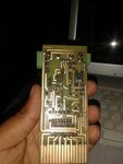
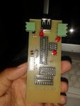
I was working on a project that operates 8 relays using shift register and uln2803. The circuit work fine on breadboard but on PCB it didnot work. i have check it many times on Breadboard it works. but didnot work on PCB. Any help. i am using Atmega 328 standalone with 16 Mhz crystal and 33pf capacitors, 74HC595 shift register, uln2803 dalignton array,
 

Do you know if the oscillator is running? A schematic might help.
 

here is the pcb design
 

Attachments

  • 11148610_10204245632522618_5462946831069952720_n.jpg
    11148610_10204245632522618_5462946831069952720_n.jpg
    70.9 KB · Views: 52
  • 11263062_10204245632802625_487513462007804283_n.jpg
    11263062_10204245632802625_487513462007804283_n.jpg
    60 KB · Views: 57

To refer to the question that is addressed in the question title but hasn't beem further discussed yet:

Datasheet says capacitors should be 12 - 22 pF with 16 MHz crystal. There's a certain chance that the crystal doesn't run due to wrong capacitor value. Other possible problems are not deasserting reset (if it's enable in the fuses) and all kinds of fuse configuration erorrs in general. If you're unsure about the crystal oscillator circuit, you can test the circuit with internal RC first.
 

Basic debug is verify all DC and gnd and no unterminated inputs on CMOS.
Was it ever exposed to ESD during assembly, test?
Then probe logic levels on all pins including clock, which may be Near Vcc/2 on output if no scope.
 

Hi,

doesn't run due to wrong capacitor value.

I also was confused some tine ago..
When a crystal datasheet speaks of 12 .. 22pF load capacitance, then it is for a single "parallek" capacitor.
But usually one uses two capacitors with a "pierce oscillator circuit" acting both in series.
Then each capacitor needs about twice the value given in the datasheet.
Exact calculation takes stray capacitance and inverter input and output capacitors into account.

https://www.crystek.com/documents/appnotes/PierceGateLoadCap.pdf

Klaus
 

Must be a basic layout flaw. As most AT cut fundamental crystals can be pulled >+\-100ppm using 1/4 to 4x load capacitance with sufficient CMOS gain in logic chip.

What is the clock out Vdc level?
 

Status
Not open for further replies.

Similar threads

Part and Inventory Search

Welcome to EDABoard.com

Sponsor

Back
Top