Continue to Site

Welcome to EDAboard.com

Welcome to our site! EDAboard.com is an international Electronics Discussion Forum focused on EDA software, circuits, schematics, books, theory, papers, asic, pld, 8051, DSP, Network, RF, Analog Design, PCB, Service Manuals... and a whole lot more! To participate you need to register. Registration is free. Click here to register now.

Charlieplexing Seven segment led problem?

Status
Not open for further replies.

hemnath

Advanced Member level 3
Joined
Jun 24, 2012
Messages
702
Helped
61
Reputation
120
Reaction score
57
Trophy points
1,308
Location
Chennai
Activity points
6,588
hi,
I'm using PIC18LF2520. Internal oscillator: 1Mhz, CCS C Compiler
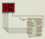
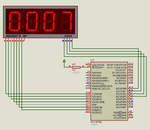
I'm using charlieplexing method to display the numerals in the Seven Segment display (SSD). SSD is of type Common Anode.
Below is the sample Code:
HTML:
#include "18F2520.h"
#fuses INTRC_IO
#use delay(clock=1000000)

#use fixed_io(b_outputs=PIN_B4,PIN_B5,PIN_B6,PIN_B7) 
 
const char DIGIT_ZERO[] =    {
                     //     gfedcba

                        0b11111110,       //   a
                        0b11111101,         //   b
                        0b11111011,         //   c
                        0b11110111,         //   d
                        0b11101111,         //   e
                        0b11011111,         //   f
                        0b11111111         //   g
                     };      

const char DIGIT_ONE[] =    {
                     //     gfedcba

                        0b11111111,       //   a
                        0b11111101,         //   b
                        0b11111011,         //   c
                        0b11111111,         //   d
                        0b11111111,         //   e
                        0b11111111,         //   f
                        0b11111111         //   g
                     };                           

const char DIGIT_TWO[] =    {
                     //     gfedcba

                        0b11111110,       //   a
                        0b11111101,         //   b
                        0b11111111,         //   c
                        0b11110111,         //   d
                        0b11101111         //   e
                        0b11111111,         //   f
                        0b10111111         //   g
                     };   

const char DIGIT_THREE[] =    {
                     //     gfedcba

                        0b11111110,       //   a
                        0b11111101,         //   b
                        0b11111011,         //   c
                        0b11110111,         //   d
                        0b11111111,         //   e
                        0b11111111,         //   f
                        0b10111111         //   g
                     };

const char DIGIT_FOUR[] =    {
                     //     gfedcba

                        0b11111111,       //   a
                        0b11111101,         //   b
                        0b11111011,         //   c
                        0b11111111,         //   d
                        0b11111111,         //   e
                        0b11011111,         //   f
                        0b10111111         //   g
                     };

const char DIGIT_FIVE[] =    {
                     //     gfedcba

                        0b11111110,       //   a
                        0b11111111,         //   b
                        0b11111011,         //   c
                        0b11110111,         //   d
                        0b11111110,         //   e
                        0b11011111,         //   f
                        0b10111111         //   g
                     };

const char DIGIT_SIX[] =    {
                     //     gfedcba

                        0b11111110,       //   a
                        0b11111111,         //   b
                        0b11111011,         //   c
                        0b11110111,         //   d
                        0b11101111,         //   e
                        0b11011111,         //   f
                        0b10111111         //   g
                     };

const char DIGIT_SEVEN[] =    {
                     //     gfedcba

                        0b11111110,       //   a
                        0b11111101,         //   b
                        0b11111011,         //   c
                        0b11111111,         //   d
                        0b11111111,         //   e
                        0b11111111,         //   f
                        0b11111111         //   g
                     };

const char DIGIT_EIGHT[] =    {
                     //     gfedcba
                        0b11111110,       //   a
                        0b11111101,         //   b
                        0b11111011,         //   c
                        0b11110111,         //   d
                        0b11101111,         //   e
                        0b11011111,         //   f
                        0b10111111         //   g
                     };

const char DIGIT_NINE[] =    {
                     //     gfedcba

                        0b11111110,       //   a
                        0b11111101,         //   b
                        0b11111011,         //   c
                        0b11111111,         //   d
                        0b11111111,         //   e
                        0b11011111         //   f
                        0b10111111         //   g
                     };

unsigned int16 value = 0, temp_value = 0, value1 = 0, count = 0;
unsigned int16 increment = 0, DIGIT_VALUE = 0;
int1 DIGIT_FLAG = 1;
int1 UP_FLAG = 1;
unsigned int disp_value1, disp_value2, disp_value3, disp_value4;
unsigned int16 DIGIT_VAL;

void display_value();
void digit(int16 DIGIT_VALUE);
void segment(int16 digit);

#INT_TIMER1
void timer1_isr()
{
	if(interrupt_active(INT_TIMER1))
	{
		count++;

		if(count > 6)
		{
			INCREMENT++;
			count = 0;
		}

		if(INCREMENT == 0)
		{
			output_b(0b00010000);		// 1st digit
			DIGIT(disp_value4);    			// 
		}   
			
		if(INCREMENT == 1)
		{
		   	output_b(0b00100000);
		  	DIGIT(disp_value3);    
		}
		
		if(INCREMENT == 2)
		{
		   	output_b(0b01000000);
		  	DIGIT(disp_value2);    
		}
		
		if(INCREMENT == 3)
		{
		   	output_b(0b10000000);
		   	DIGIT(disp_value1);    
		}

      if(INCREMENT > 3)
      {
         INCREMENT = 0;
      }

      set_timer1(0xFF05);         // 1ms for 1Mhz
      clear_interrupt(INT_TIMER1);
   }
}   

#INT_EXT
void ext_interrupt_isr()
{
   DIGIT_FLAG = 0;
}

#INT_EXT1
void ext_interrupt_isr1()
{
   UP_FLAG = 0;
}

void main()
{
	set_tris_a(0xFF);
	set_tris_b(0x00);
   setup_comparator(NC_NC_NC_NC);

   setup_timer_1(T1_INTERNAL|T1_DIV_BY_1);
   set_timer1(0xFF05);       // 1ms for 1Mhz
   ext_int_edge(H_TO_L);
   enable_interrupts(INT_EXT);

   ext_int_edge(H_TO_L);
   enable_interrupts(INT_EXT1);

   #priority TIMER1, EXT, EXT1

   enable_interrupts(INT_TIMER1);
   enable_interrupts(GLOBAL);
   
   count=0;

   INCREMENT = 0;
   DIGIT_VALUE = 0;

		DIGIT_VAL = 1234;
		
		disp_value1 = (DIGIT_VAL%10);
		disp_value2 = ((DIGIT_VAL/10)%10);
		disp_value3 = ((DIGIT_VAL/100)%10);
		disp_value4 = ((DIGIT_VAL/1000)%10);

   while(1)
   {
        // To display 1234 in Seven segment display 

	}
}


void DIGIT(int16 DIGIT_VALUE)
{
	
	switch (DIGIT_VALUE)
	{	
		case 0:	output_a(DIGIT_ZERO[count]); 
				break;

		case 1: output_a(DIGIT_ONE[count]); 
				break;

		case 2: output_a(DIGIT_TWO[count]);    
				break;

		case 3: output_a(DIGIT_THREE[count]);  
				break;

		case 4: output_a(DIGIT_FOUR[count]);
				break;		

		case 5: output_a(DIGIT_FIVE[count]);
				break;

		case 6: output_a(DIGIT_SIX[count]); 
				break;

		case 7: output_a(DIGIT_SEVEN[count]);  
				break;

		case 8: output_a(DIGIT_EIGHT[count]);
				break;

		case 9: output_a(DIGIT_NINE[count]);
				break;		
	}
}
Problem noticed: I want to display 1234 in display. But the LED's are blinking at the fast rate. I have set up the interrupt to 1ms.
Does anyone knows any other method to use charlieplexing?
Please help
 

charliplexing. Switching ON one segment at one time. NOT ALL SEGMENTS. I'm working on hardware. I dont have proteus file right now.
 

Looks like complicated way of doing things! 'Charlieplexing', although not a true technical name, is normally used when the polarity fed to the LED is reversed. It allows twice as many LEDs to be used by wiring them in reverse parallel. What you are doing is multiplexing the segment signals.

Brian.
 

Normally multiplexing seven segment displays requires more current (i.e, to display 0 in display. a,b,c,d,e,f to be switched ON, Thus increases the power). In my situation, where i have only 5 mA to power all LED and im using 4 seven segment LEDs to display 4 numerals. without charliplexing method, how can be done?
I had a search on the net and found that charlieplexing method can display the numbers in seven segment with minimum power.

for reference: https://www.instructables.com/id/Multiplexing-7-Segment-displays-with-Arduino-and-S/

I can feed only minimum current to power the LEDs . Please help
 

Are you telling that a Seven segment digit has 7 segments and you want to turn on one segment of a digit for a short time and do both multiplexing and charliplexing? 5 mA is too low for an LED. It needs atleast 10 mA for good brightness.

To do what you want you have to send each bit of the mask to PORTB's corresponding bits. If you want to display digit 8 mask is 0x80, so, abcdefg are all 0's. If you place 0x00 on PORTB (data lines) then you are turning OFF all pins of PORTB i.e., abcdefg. It doesn't make any difference. You can't use just 1 pin to send data of abcdefg as they all need seperate lines.
 
Last edited:

I have super bright Seven segment LED display. luminous intensity @ 10mA is 120000 .. I have checked with allowing 2mA to LED, it is brighter than the normal LED displays.
 

Ok. I will debug you code and see what is happening but to do that you have to zip and post the project files and not just .c file. Also post an image of circuit.


Edit: I did a 2 digit SSD Charliplexing + Multiplexing and it took 45 minutes. Working code attached.


Edit2: Modified the code to 4 digits. Took 5 minutes. Not tested in hardware. Test and reply.

99016d1385384333-cp.png


99018d1385384905-cp4d.png
 

Attachments

  • Charliplexing 2D SSD.rar
    45.8 KB · Views: 107
  • cp.png
    cp.png
    22.7 KB · Views: 186
  • Charliplexing 4D SSD.rar
    63.8 KB · Views: 107
  • cp4d.png
    cp4d.png
    27.7 KB · Views: 165
Last edited:
hi jayanth,
Thanks for sparing your time for my work.

I have tested your program in real hardware rather than simulating in proteus. Problem noticed: Display is flickering.
Also noticed you have used 4Mhz clock. I have already tested my program with 4Mhz & 2Mhz internal oscillator, it is working good in hardware. To reduce the current consumption of the micro-controller, i'm in need of using internal 1Mhz oscillator. When i simulate the program with 1Mhz crystal, display starts flickering. I need some good logic in program to work with 1Mhz oscillator.
Thanks :)

- - - Updated - - -

changed isr routine to happen every 250us with 2Mhz oscillator. working great. Thanks.
But i have one problem, same program is programmed in PIC18LF2520, segment b is not at all glowing. I measured the signal on the scope, it is showing some junk waveform on segment b.

Why it is so?
 

My code was for PIC18F452. Did you recompile my code for your PIC? Zip and post your project files. I will test it. Post all project files and not just .c file. The uC pin connected to segment b might be open drain pin. Use a pull-up resistor on segment b line and see.

Did you try with LATx instead of PORTx?
 
Last edited:

hemnath requested help on charliplexing and I think with charliplexing for 4 SSD, with the decimal ignored, it should be implemented with only 8 pins not 9, 10 or 11, that is the whole Idea of Charliplexing, minimizing pin count. So on jayanth.devarayanadurga's schematic the common Anode/cathodes on PORTD should be connected any pins on PORTB. Possible to get results on Controllers with a three state Pins.
 

Thanks jayanth.. I will use pull up resistor and check it once with PIC18LF2520.
How to increment digits[0] , digits[1], digits[2], digits[3] individually?
 

How to increment digits[0] , digits[1], digits[2], digits[3] individually?

Individually or manually?

digits contains the value of variable number split into digits. Why do you want to increment or decrement it individually. If the number changes then the digits also change.
 

i want to increment the digits individually.i.e., i have 2 buttons. One button will select the digit. Another button will increment or decrement the selected digit.

- - - Updated - - -

In a Seven segment digital clock, where the individual digit values can be changed using the buttons. I want to increment similar to that. But im not designing a clock now.
Intention is, to increment the value on seven segment.
 

Do something like this.


Code C - [expand]
1
2
3
4
5
6
7
8
9
10
11
12
13
14
15
16
17
18
19
20
21
22
23
24
25
26
27
28
29
30
31
32
33
34
35
36
37
38
39
40
41
42
43
if + button pressed
 
    switch(digit){
 
         case 0:
                    temp = (digit[0] % 10);
                    digit[0] = (temp <  9)? digit[0] + 1 : digit[0] - temp ;
                    break;
             case 1:
                    temp = (digit[1] / 10) % 10;
                    digit[1] = (temp <  9)? digit[1] + 10 : digit[1] - (temp * 10);
                    break;
             case 2:
                    temp = (digit[2] / 100) % 10;
                    digit[2] = (temp <  9)? digit[2] + 100 : digit[2] - (temp * 100);
                    break;
             case 3:
                    temp = digit[3] / 1000;
                    digit[3] = (temp <  9)? digit[3] + 1000 : digit[3] - (temp * 1000);
                    break;
    };
 
if - button pressed
 
    switch(digit){
 
         case 0:
                    temp = (digit[0] % 10);
                    digit[0] = (temp)? digit[0] - 1 : digit[0] + 9 ;
                    break;
             case 1:
                    temp = (digit[1] / 10) % 10;
                    digit[1] = (temp)? digit[1] - 10 : digit[1] + 90;
                    break;
             case 2:
                    temp = (digit[2] / 100) % 10;
                    digit[2] = (temp)? digit[2] - 100 : digit[2] + 900;
                    break;
             case 3:
                    temp = digit[3] / 1000;
                    digit[3] = (temp)? digit[3] - 1000 : digit[3] + 900;
                    break;
    };

 
thanks jayanth. I did something like this and it is working.
HTML:
	digits[0] = digits[0] + 1;
	if(digits[0] > 9)
	{
		digits[0] = 0;	
	}[/HTML
same routine followed for digits[1], digits[2], digits[3]. Well, my routine will make any problem??? 

Now i met with another problem. I want to blink 1st digit. how to do that?
 

Your code does the same which my code does but the code is written in a different way using ternary operator.

Do you want to display all digits but blink only the digit being set or do you want to display and blink only the digit being set?

If 1 then when the isr displays the digit being set then toggle the display enable/disable pin which is common anode pin of that digit at the blinking speed you want. Maybe you need to use another timer for this blinking.

If 2 then same as above but display other digits is disabled i.e., digits switching is not needed while setting.
 
Hi, thanks jayanth.
i have done the blinking part as you suggested.

But when i write a data on eeprom. Display is blinking. Please check the attached file.
 

Attachments

  • SSD - Edaboard.zip
    45.1 KB · Views: 98

Your code is very lengthy. i is used to select a particular digit (SSD). What is j used for?

You can do it like this...

No need for two different codes for blinking that is while incrementing and decrementing.

Use two flags one for incrementing and one for decrementing.

When any one of these flags is set then a variable will select the digit (SSD) to be incremented or decremented and this variable say update is incremented and cycles when select digit (SSD) button is repeatedly pressed.

You will need 4 instructions to vary the 4 digits of a number as I provided earlier.

In isr timer runs only in blink mode and toggles the blink flag and also in isr if blink flag is set particular display is ON for 1 sec say and then blink flag is reset. The second timer interrupt which displays data should display data based on the value of blink flag.

As I said earlier you need 2 timers one for display data and one for blink delay.
 

Status
Not open for further replies.

Similar threads

Part and Inventory Search

Welcome to EDABoard.com

Sponsor

Back
Top