Continue to Site

Welcome to EDAboard.com

Welcome to our site! EDAboard.com is an international Electronics Discussion Forum focused on EDA software, circuits, schematics, books, theory, papers, asic, pld, 8051, DSP, Network, RF, Analog Design, PCB, Service Manuals... and a whole lot more! To participate you need to register. Registration is free. Click here to register now.

Charging cap in quickest time

Status
Not open for further replies.

carlmbecker

Newbie level 6
Joined
Aug 8, 2010
Messages
12
Helped
1
Reputation
2
Reaction score
1
Trophy points
1,283
Activity points
1,348
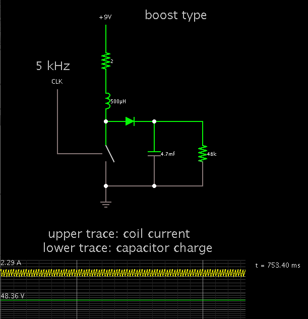
I am looking for some help in determining inductor (physically small as possible) and frequency etc. to charge about a 4700uF cap in about 0.8seconds (800mS) to a level of 48Volts with a 9V power source. - thanks in advance cb

i.e. Step up converter from 9V to 48V capable of charging 4700uF in 0.8 seconds.
 
Last edited:

There is a formula but I couldn't figure out which one to use, so I cheated and used a simulator.

I had to increase the henry value several times to slow down the capacitor charging so it was at 9V after .8 sec.

It will not be a small inductor. Something on the order of tens of henries. If you were to break the circuit at an unfortunate moment, it would generate a hi-V kick that could be lethal.

Since you want small size you probably will want to use a gyrator circuit. This mimics is an inductor by using an op amp and capacitor. It will be feasible because current flow is less than 84 mA.

Looking at the resulting sine waveform, I now see the formula has to do with finding what henry value results in LC tank oscillations with a period of 4 times .8 sec.

Or are you asking about a resistor?

Then you want about 5 time constants to occupy .8 sec. (According to convention)

This makes the time constant .8/5, or .16.

To solve for R using the RC time constant formula, we take .16 and divide by the capacitor value.
 

There is a formula but I couldn't figure out which one to use, so I cheated and used a simulator.


To solve for R using the RC time constant formula, we take .16 and divide by the capacitor value.

************************************************************************************
Thanks - I did forget to mention I need to charge the cap up to 48V. This may change quiet a few things
 

You have to store about 5.4J. Depending on the tolerance of the capacitor, it may be more (say 8J). You want to transfer the energy in 0.8s, so that means the charging power should be in the range of 6.7 to 10W.

I would go for some boost converter topology (maybe with an autotransformer to get reasonable duty cycle) that controls on input current (in your case about 1A). Controlling based on input current (that is the current taken from the 9V supply) gives the lowest peak power. Termination you can do based on voltage with some hysteresis so when the capacitor voltage drops too much, it will be charged again.
 

To demonstrate how a boost converter might perform to your specs, here's a screenshot of my simulation.

The capacitor has reached 48V after .8 seconds.


Not shown is the beginning of the cycle. Initial current was over 4 A. (A boost converter allows current through the coil and capacitor no matter whether the switching device is on or off.) The capacitor quickly acquired a charge of several volts.

After a while current dropped to 2.2A. If your 9V supply can provide this then such a circuit could work.

A proper control circuit needs to be added to limit peak current. This would automatically alter frequency and/or duty cycle.
 

In case your 9V supply can only provide 1.6A, this is a next step toward a working circuit.

I added an op amp and transistor. For some reason it can use a lower peak current than my above schematic.


This still needs auto shut-off, because otherwise the capacitor charge will continue rising indefinitely.

The left-hand scope trace shows the entire cycle. A large current burst occurs at powerup. However the real amount will be limited by internal resistance in the 9V supply.
 

In case your 9V supply can only provide 1.6A, this is a next step toward a working circuit.


The left-hand scope trace shows the entire cycle. A large current burst occurs at powerup. However the real amount will be limited by internal resistance in the 9V supply.

Thanks very much BtR - this is great and very helpful. For interest what simulation package are you using ?
 
Last edited:

Thanks very much BtR - this is great and very helpful. For interest what simulation package are you using ?

It's the animated simulator at Paul Falstad's website:

www.falstad.com/circuit

You can interact with it by changing values, speed, etc. You can construct circuits of your own, as well as run the ones provided.

Right-click on a component, to bring up an edit window. Press Ctrl and drag to place components.

The link below will open the falstad.com site, load my schematic and run it on your computer.

Click Allow to permit the connection.

https://tinyurl.com/c7gelns
 

Status
Not open for further replies.

Part and Inventory Search

Welcome to EDABoard.com

Sponsor

Back
Top