Vermes
Advanced Member level 4
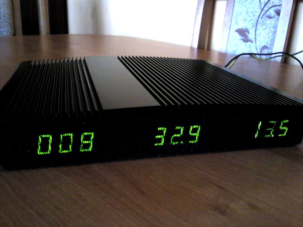
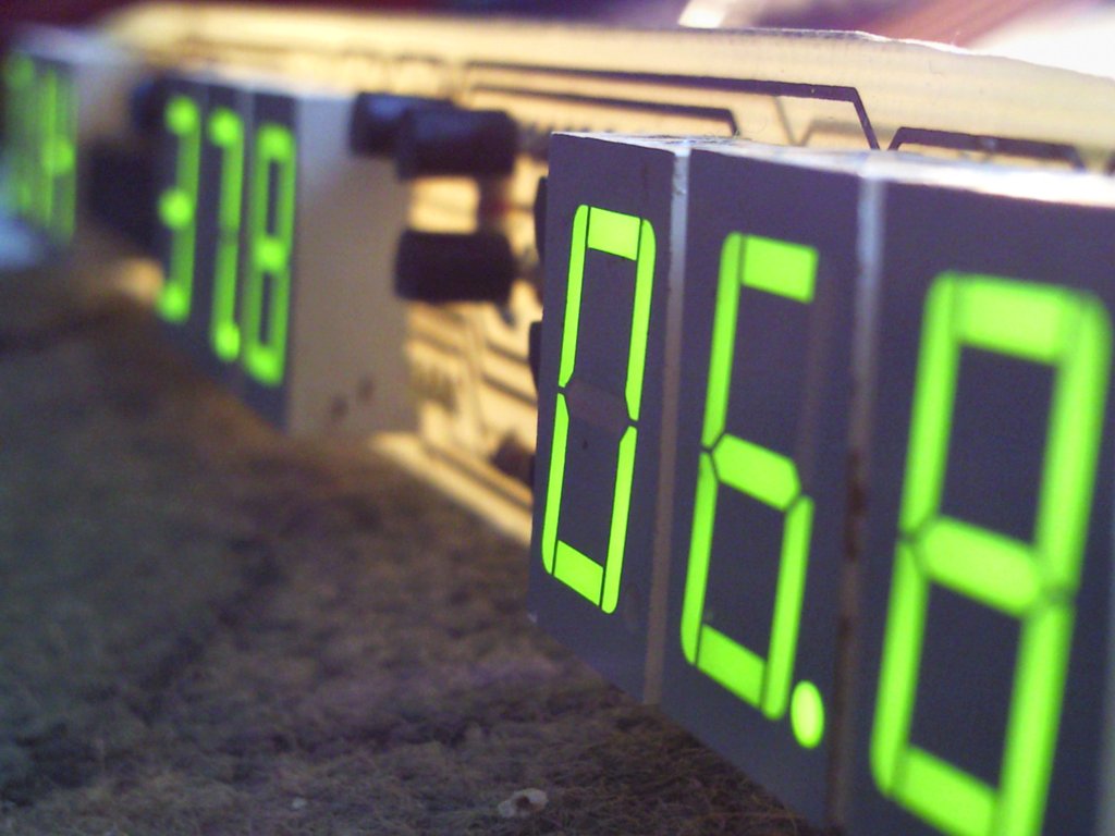
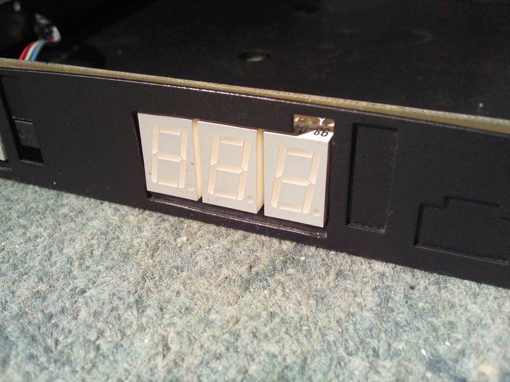
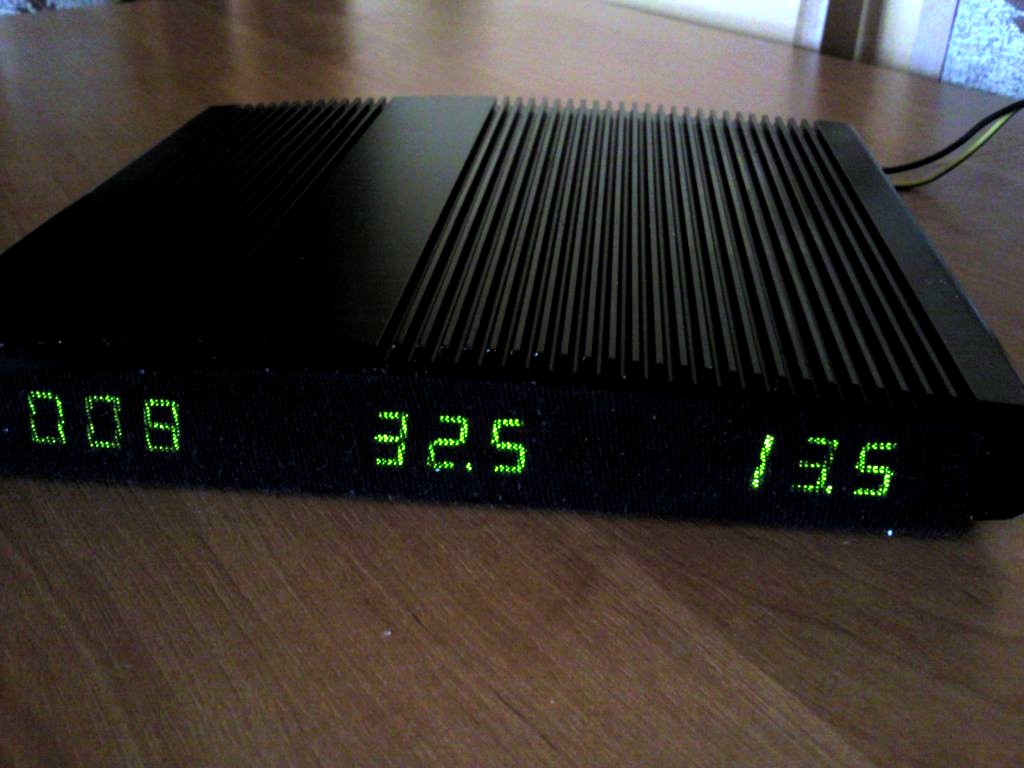
It is a car amplifier with a power of 400W. The device is based on the push-pull converter on system KA7500 (TL494) with a power of up to 500W, allowing four power amplifiers TDA7294. The amplifier has three 3-digit LED displays on the front panel. They display current voltage of the power supply, temperature of the amplifier and its estimated outgoing power.
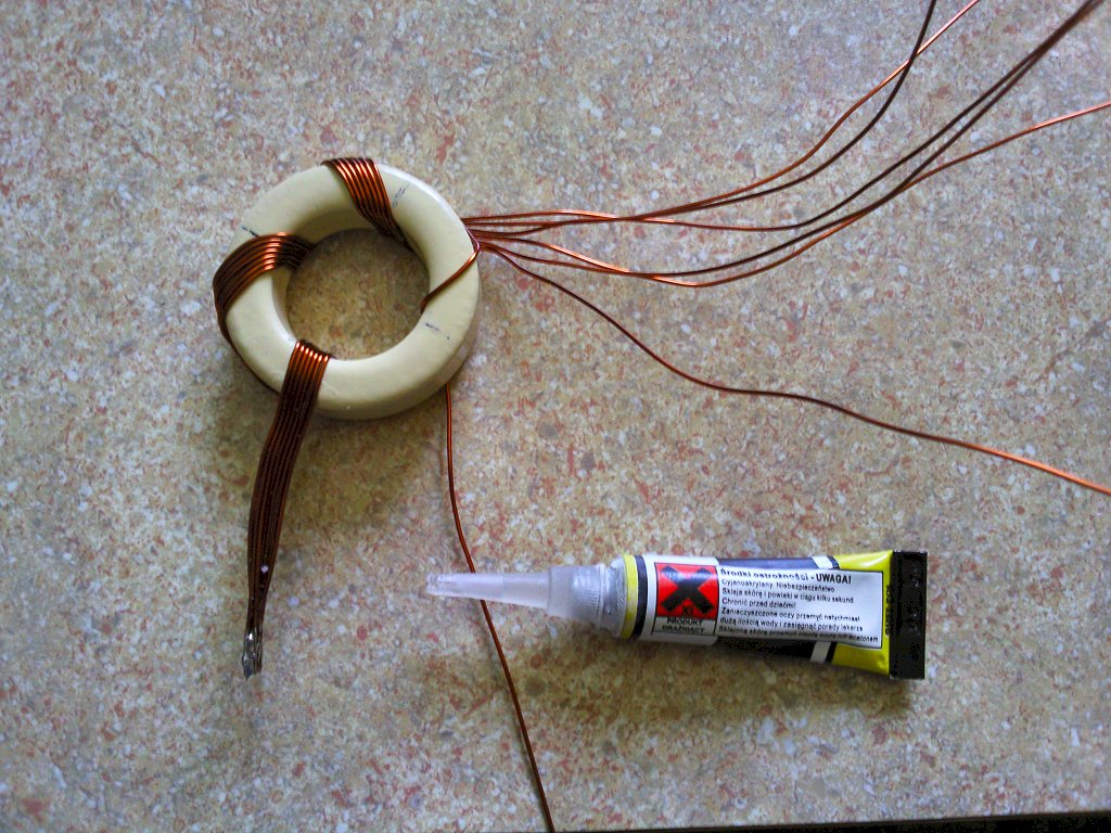
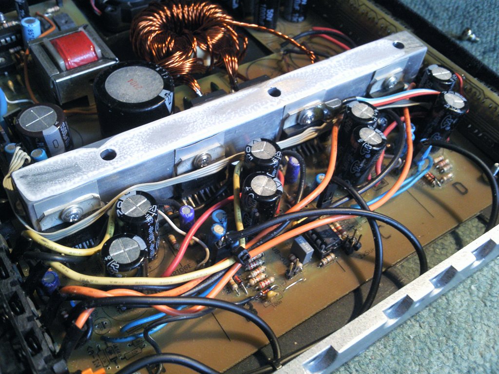
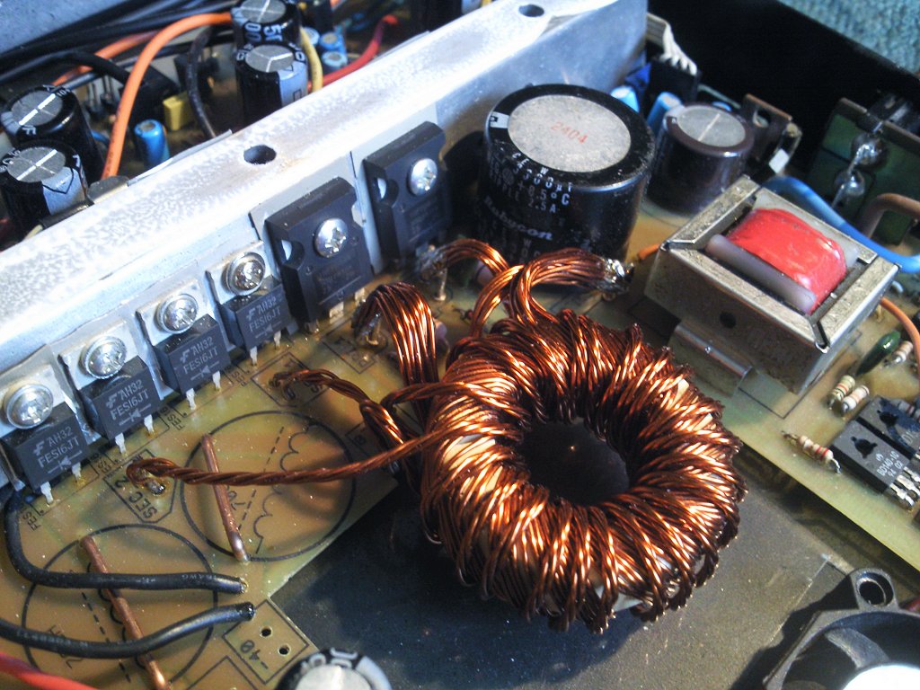
Voltage converter:
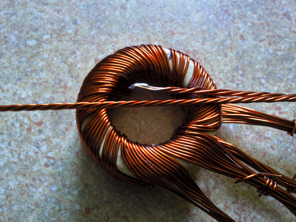
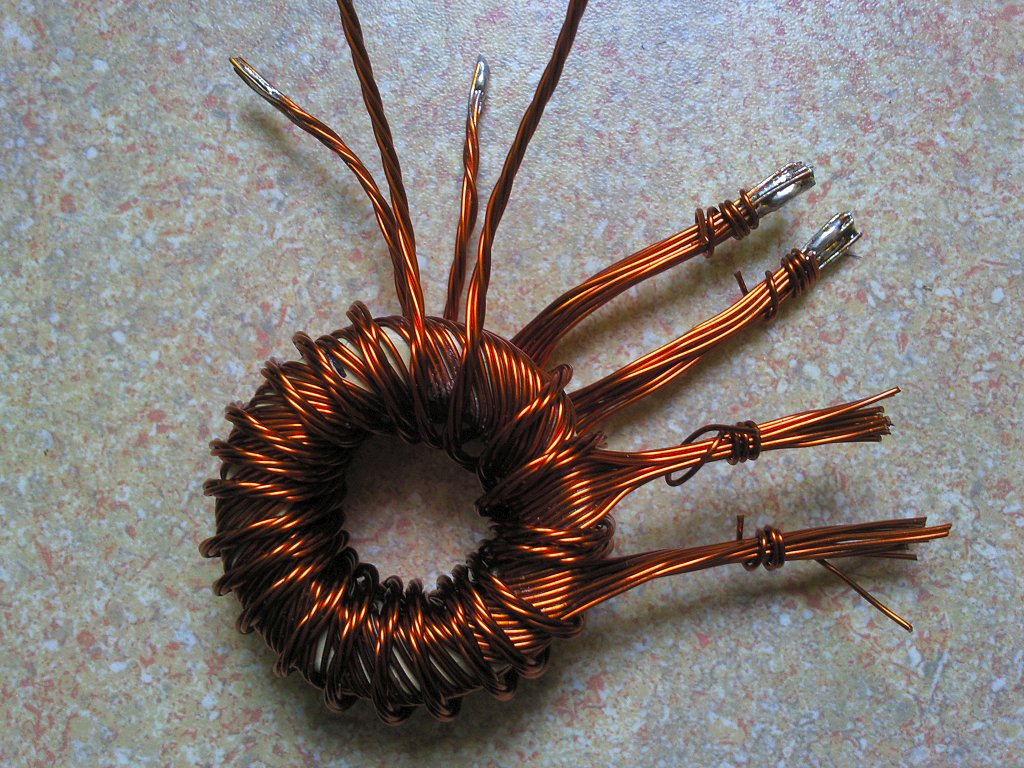
The whole is based on AVT2732 kit. The converter based on the driver KA7500 (TL494), frequency of operation is 30KHz (1.5nF + 10K). This system controls the keys IRFP064N of the allowable continuous current up to 110A. Unfortunately, these keys have a large capacity of the gate and it is necessary to use duplicates. Two pairs of bipolar transistors BD140 and BD139 work as such duplicates. Rectifying diodes are fast diodes FES16, followed by the capacitor bank. Next thing was the matter of transformer. Toroidal core TX42 (TX42/13/26) was used. The transformer is wounded by a wire with a diameter of 0,7mm. The primary winding: 4 coils, 20 wires, biphilary. The secondary winding: 11 coils, 6 wires, biphilary. This configuration allows to achieve idle voltage of +-40V at the output, with 14,5V input voltage. Exceeding the input voltage above 15V cause the activation of the overvoltage protection and shut down the converter. Lower threshold of the security response is the value 9V, it protects against excessive battery discharge. The driver of the inverter is powered by REMOTE line from the car radio – current consumption of this line is about 45mA.
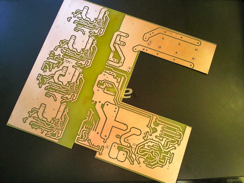
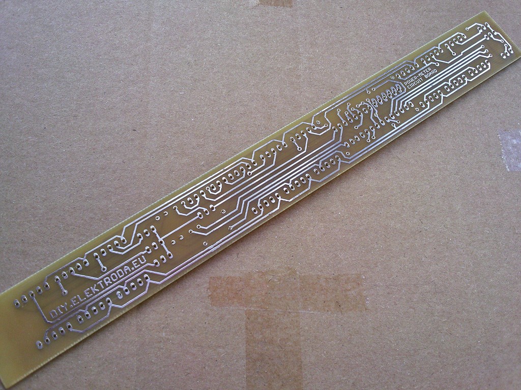
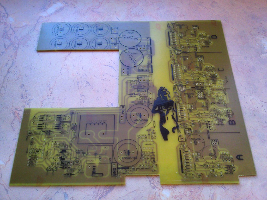
The board in the pictures differs from the board from its final version in the attachment, because it was changed after tests.
Power amplifiers:
Power amplifiers are TDA7294 chips. They are simple, cheap and publicly accessible. Power of each of them, theoretically, is 100W. The measured power is equal to 85W per channel – the distortion of 1%. Power amplifiers operate in the standard application with slightly modified control of ST-BY and MUTE lines, so that the power amplifiers faster disable after cutting off the power. For this purpose 1N1418 diode was added on MUTE line. Cubes are controlled in pairs, the channel A, B and C, D have a common ST-BY and MUTE line. On the board, next to the pin connectors to provide the input signal, there are jumpers by which the power amplifiers can be reconfigured quickly to bridge work. You can jumper channels A with B and C with D. To do this, the signal should be given only on the first channel (A or C), and two jumpers labelled (“bridge A+B”, “bridge C+D”) on the second channel (B or D), one on the pins that were the input of the signal and the second on two adjacent through which the reverse signal will flow from the output of the first input power amplifier to the second. Of course, after such treatment, the speaker can be connected.
In addition, there is low-pass filter on the board, with cut-off frequency of about 80Hz. It can be used freely, for example, the output signal can be given to bridged channels and those used as a subwoofer output. It is powered by +12V -12V.
The meter on the front panel and the current measurement:
The meter was based on Atmega8 microcontroller with program written in Bascom. The microcontroller controls the LED displays via multiplexing – that is at once only one display lights. For this reason, the displays poorly light, so the segments current limiting resistances should be as small as possible – on the diagram the safe value is 100ohm. It is good to choose them by the maximum instantaneous current that the display can take. Temperature measurement is carried out on a digital sensor, popular DS18B20. Voltage measurement by precision potentiometer 100K working as voltage divider plugged right next to the power terminals, and with 100uF capacitor forms a RC filter averaging the results. The divider is set so that 17V at the input, 5V is received for ADC. Current measurement is carried out by measuring the voltage drop at the measuring path, the measurement on the mass (mass path between capacitors C11 and C12).
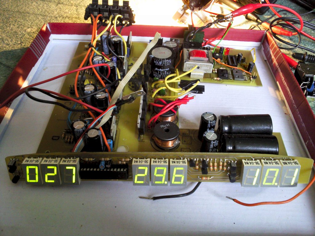
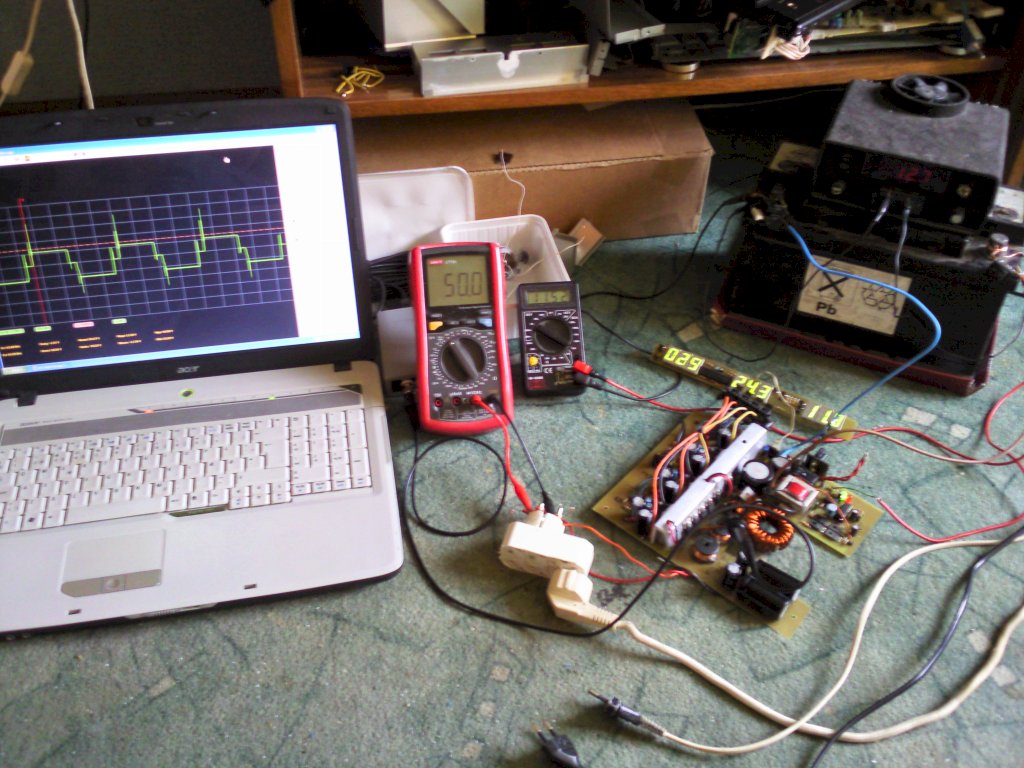
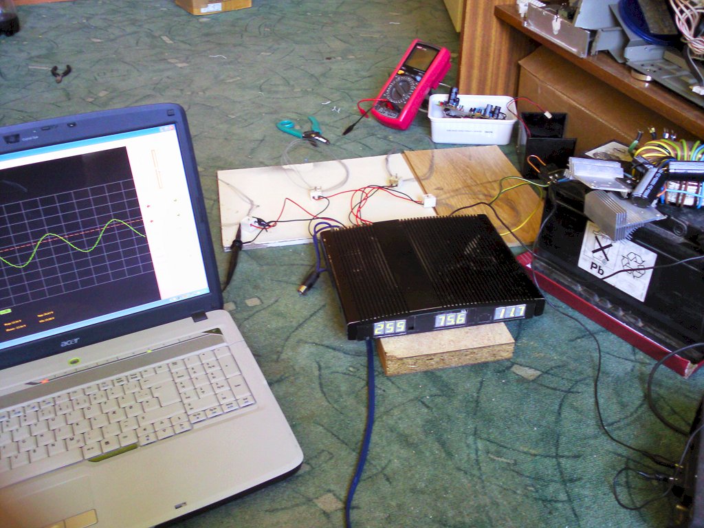
The path resistance was experimentally set by soldering next copper wires, and each 1A of current is 1mV of the voltage. So for 50A current the voltage drop on this path will be only50mV. This will not result in the heating and thus the temperature drift. Such a small decrease is also significant for the work of the amplifier, each tiny drop is 2,75 times greater decrease in the other side. Operational amplifier LM358 increases the voltage of the measuring path 100 times, so for 50A the drop is 50mV and 5V at the output for ADC of the microcontroller. In addition, the increase can be calibrated via the precision potentiometer 100K, and placed on RC filter (100K and 100uF) averages the result. This amplifier has the bipolar transistors PNP at the input, so it can operate with input voltages equal to 0V (negative voltage of the amplifier's power supply, here GND). Efficiency of the power amplifiers was started at 70%, the program first multiplies the current value by the input voltage to give the consumed power, then the same power amplifiers efficiency is credited. The program does not count the average value – averaging the results is carried out by analogue RC filters. The program was calibrated using a constant load – 4 bulbs 60W/12V – connected at the second filter capacitor at the end of the measuring path. The meter showed almost perfectly the consumed power – but when the load was added in the output of the inverter – the result was inflated. Despite a good filter, distortions of the inverter makes some trouble. The front panel is powered by a 7805 type stabilizer, activated by BD135 remote line of the transistor. From the transistor, the current flows to the internal ventilator.
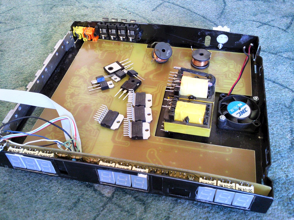
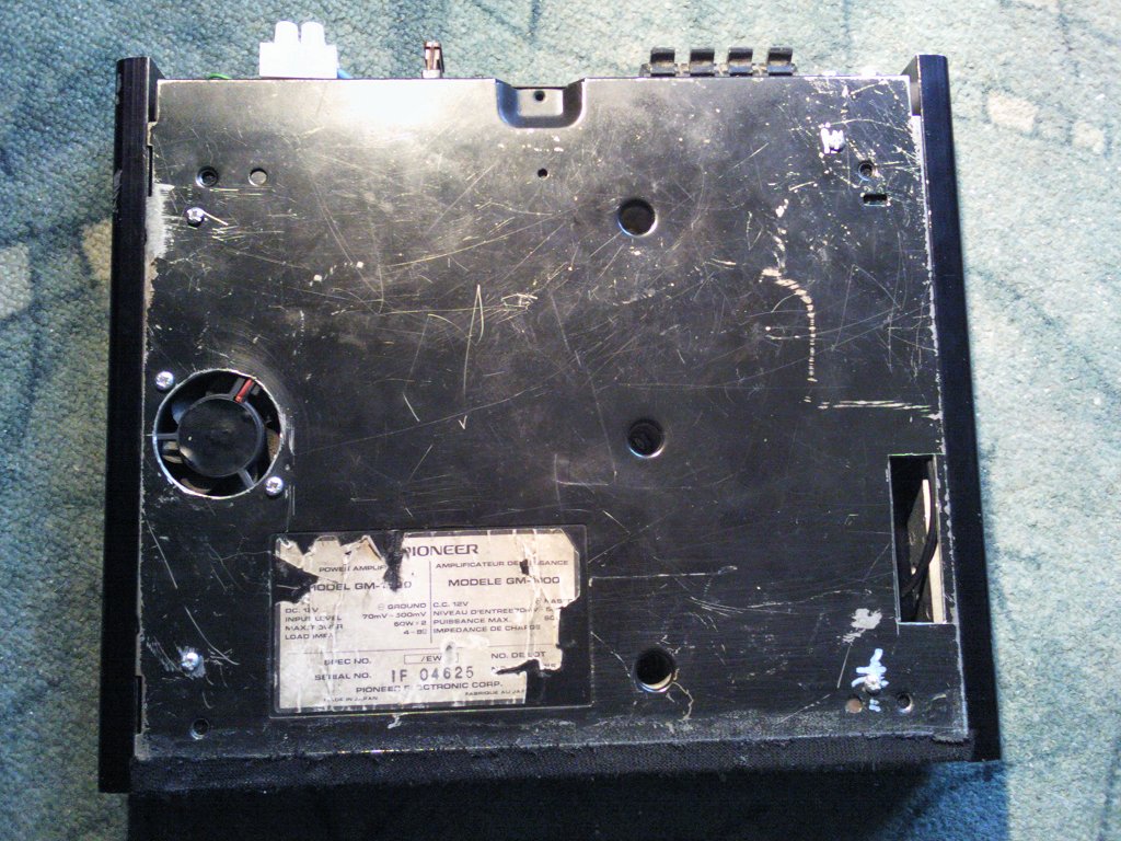
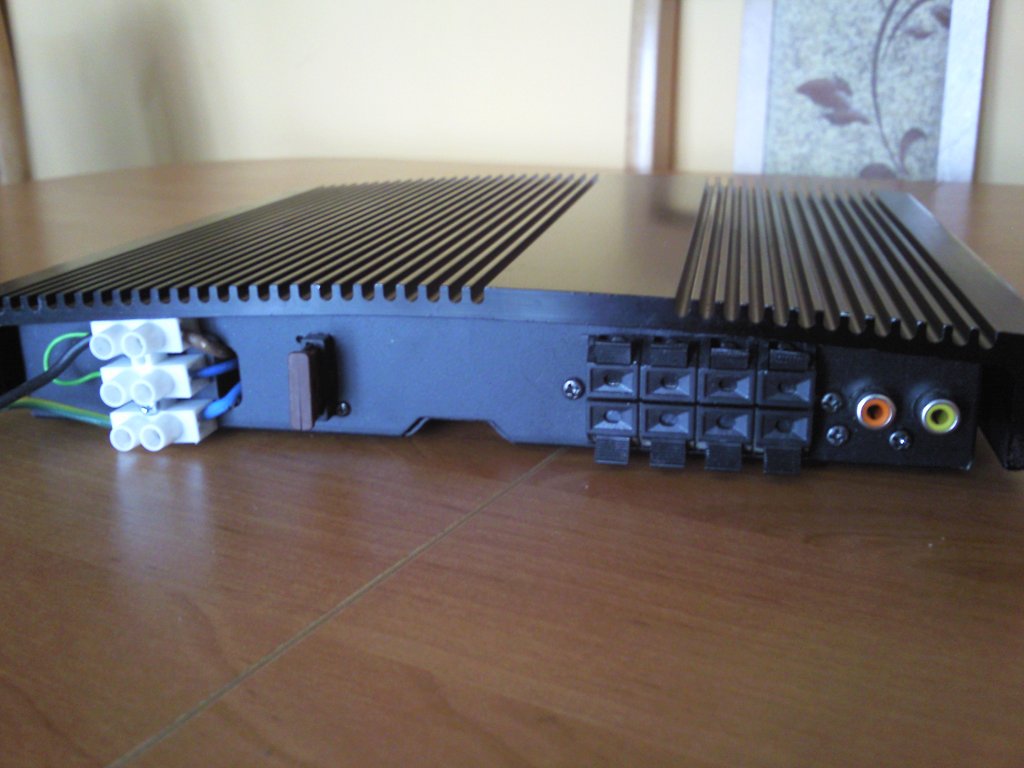
Housing:
The housing is from an old car amplifier pioneer GM-1000. Also few passive parts were taken from it. The whole frame with PCB was cut, in the front panel, the holes for 7-segments displays were cut. On the other side, a new hole for the fuse socket and hole for connector socket for speakers and two cinch sockets. The front panel is covered with black material stretched so that it looks uniform and only when turned, it turns out that the amplifier has hidden displays. All power amplifiers, the keys of the inverter and rectifier diodes were tightened to the middle section aluminum by silicone pads. This section gives the heat to the upper lid of the amplifier – a thermal combination improved with silicone paste.
The amplifier needs a good active cooling, for this purpose a 120mm fan was mounted outside. Inside there is additional ventilator 40mm. Unfortunately this is not enough for the amplifier to work at full power. At 75% power and continuous operation, after half an hour, the housing heats up to 91 degrees Celsius. Above this temperature in the power amplifiers thermal protection begins to operate and the amplitude of the output signal begins to be reduced.
Notes:
Power cable from the battery should be minimum cross section 20mm2. External fuse – 50A. When constructing and using the amplifier, you have to pay attention, because such current is dangerous. The amplifier cannot adhere with the underside to the floor, because it would block the ventilation holes. Few connections on the board should be made by cables – they are marked red.


Link to original thread (attachment) – Wzmacniacz samochodowy 4x100W