Continue to Site

Welcome to EDAboard.com

Welcome to our site! EDAboard.com is an international Electronics Discussion Forum focused on EDA software, circuits, schematics, books, theory, papers, asic, pld, 8051, DSP, Network, RF, Analog Design, PCB, Service Manuals... and a whole lot more! To participate you need to register. Registration is free. Click here to register now.

Capacitor with neon lamp circuit

Status
Not open for further replies.

Teknolog

Newbie level 4
Joined
Sep 1, 2013
Messages
6
Helped
0
Reputation
0
Reaction score
0
Trophy points
1
Activity points
35
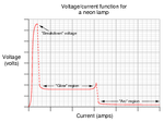
A neon lamp acts as a voltage stabilizer. No current flows through the neon lamp if the voltage across it is below a certain voltage V0. When the voltage becomes V0 a gas in the neon lamp ionizes which allows it to conduct current. When the lamp is lit it will have the voltage V0. A neon lamp is connected in the circuit shown in the illustration. In this case, V0 = 60 V, R = 100 KΩ and C = 1 μF.

00.png

a) Find the time t when the neon lamp lights up. A logarithm may be part of the answer.
b) Determine the voltage Vc(t) as a function of time. Divide the solution into two parts:
before and after the neon lamp lights up.

I manage to find out a) that the neon lamp lights up at \[t = RC*ln(2)\].

For b) that the voltage \[V_{C}(t)=2V_{0}(1-e^{-\frac{t}{RC}})\] for \[t < RC*ln(2)\].


My question is how does one calculate how to determine the voltage over the capacitor \[V_{C}(t)\] when \[t > RC*ln(2)\] ?
 

This is Audioguru using my wife's computer because my computer and my profile here are messed up.

That is an extremely old circuit.
53 years ago I made blinkers similar to yours but connected them together making a Chaser. They were powered from a 90V battery and I cast the entire circuit inside clear plastic.
Afer a few weeks one BLEW UP because its battery formed gasses. I should have added a vent.
 

My profile got messed up too, I had to re-enter my info. Weird.

But I think you're missing a piece of information: once the neon conducts, the voltage across it will drop abruptly, dependent on the device and the current through it.
 

This is just a homework task, not some thing I plan to build :)

I just need help how to find the formula for the Voltage across the capacitor (Vc(t)) after t>RC*ln(2). So if you could help me with that, that'd be great.
 

Well, if you ASSUME the voltage across the neon remains constant at V0, then voltage is simply found by:

Current through resistors is (2V0-V0)/2R.
Voltage across cap=V0+((2V0-V0/2R)*R=V0+V0/2=3/2V0

But that's not the way these things REALLY work. What REALLY happens is that the cap discharges through the neon lamp until the voltage drops low enough to turn the lamp OFF, and the cycle repeats. How much current does the lamp conduct when it switches? I don't know. I suppose for your assignment you can assume that the lamp presents a short to ground (not really true, but if makes your instructor happy...). Then you can calculate your cap voltage by replacing the neon in your circuit with a short .
 

I'm glad you try to explain how things really work. My goal is to learn how things really work. Unfortunately sometimes we get these kind of tasks where we are not supposed to really know how things work but just apply some rules we learned, in this case for transients.

According to the answer key the answer is supposed to be \[V_{C}(t)=\frac{3V_{0}}{2}-2V_{0}*e^{-\frac{2}{RC}t}\] for \[t>RC*ln(2)\].

Does this answer make sense? I don't understand how to come to it.
 

Not quite sure how this works. What that equation tells you is that at t=RC*ln(2) (when the lamp first fires), the voltage across the cap is V0 (as you'd expect, since no current flows). At the end of time (t=infinity), the voltage across the cap will be 3V0/2. That implies that the voltage at the lamp is V0. So, by cheating and working backwards, I THINK you can solve this by assuming the voltage at the lamp is always V0 after it first conducts (this is the bit of information that seems to be missing). I'm too lazy to figure this all out myself, but I'm interested to see what you come up with.

Good luck.
 

Look for Neon Bulb Voltage in Google Images then you will see a graph showing Breakdown, Glow and Arc voltages.
 

The problem setup assumes that a conducting neon drops V0 volts.

That being the case, replace the neon in the circuit with a voltage source having a voltage V0 and solve using whichever approach to circuit analysis you happen to know.

There are a couple of easy values to derive for checking your work:
First that the thing will settle to halfway between the two voltage sources (The resistors are equal after all), so 3V0/2.
Secondly that at t = RC ln (2) the thing has a voltage across the cap = V0.

HTH.

Regards, Dan.
 

Here is a graph of a neon bulb breakdown voltage and glow voltage. The voltages are listed on the datasheet of the neon bulb as a range of voltages because they are all a little different even if they have the same part number.
 

Attachments

  • neon voltages.png
    neon voltages.png
    8.8 KB · Views: 86

Dan has it. After I went back and reread the problem, it's clear that the assumption is that the voltage across the bulb is V0 when it first conducts, and for all time after that. Not a REAL neon bulb, but it sure makes the problem easier to solve.
 

Status
Not open for further replies.

Part and Inventory Search

Welcome to EDABoard.com

Sponsor

Back
Top