Continue to Site

Welcome to EDAboard.com

Welcome to our site! EDAboard.com is an international Electronics Discussion Forum focused on EDA software, circuits, schematics, books, theory, papers, asic, pld, 8051, DSP, Network, RF, Analog Design, PCB, Service Manuals... and a whole lot more! To participate you need to register. Registration is free. Click here to register now.

Capacitor with initial values

Status
Not open for further replies.

venn_ng

Member level 5
Joined
Mar 26, 2017
Messages
87
Helped
1
Reputation
2
Reaction score
1
Trophy points
18
Activity points
645
Hi,

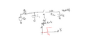
I have attached a circuit below.

Do you know what would be the closed form expression of vout (t) assuming that C1 is charged to VDD at t=0 and C2 is at 0V at t=0?
The switch turns ON at t=t1

I tried to think about it but I am not able to get a closed form expression after t=t1, as the C1 is charged to VDD (initial value). I feel like this circuit is not linear and doesn't obey superposition because of initial value of C1. What do you think?
 

Attachments

  • intesting_ckt.png
    intesting_ckt.png
    36.3 KB · Views: 115

Hi,

Looks complicated...

Wouldn't Vout equal whatever tau is reached by each capacitor respectively at t1?

C1 would discharge to x% and so to x voltage and C2 would charge to x% and so to x voltage and Vout would be C2 state of charge? Looks awfully complicated to calculate as both are dynamic values until t1 and in opposing directions?
 
The solution is the superposition of two exponential functions, but the waveform can be quite different depending on the actual RC values.
 
The solution is the superposition of two exponential functions, but the waveform can be quite different depending on the actual RC values.
Exactly, is there a closed form expression after t=t1, based on initial conditions?
--- Updated ---

Hi,

Looks complicated...

Wouldn't Vout equal whatever tau is reached by each capacitor respectively at t1?

C1 would discharge to x% and so to x voltage and C2 would charge to x% and so to x voltage and Vout would be C2 state of charge? Looks awfully complicated to calculate as both are dynamic values until t1 and in opposing directions?
lol yeah. I was breaking my head too on this ;)
 

I suppose there's a closed form solution, but I need to consult my text books or have large sheet of paper to calculate it.
 

After commutation you have 2 nodes circuit with additional voltage source in series with C1. There is nothing more than simple 2x2 matrix for nodal analysis.
 

    d123

    Points: 2
    Helpful Answer Positive Rating
Status
Not open for further replies.

Similar threads

Part and Inventory Search

Welcome to EDABoard.com

Sponsor

Back
Top