Continue to Site

Welcome to EDAboard.com

Welcome to our site! EDAboard.com is an international Electronics Discussion Forum focused on EDA software, circuits, schematics, books, theory, papers, asic, pld, 8051, DSP, Network, RF, Analog Design, PCB, Service Manuals... and a whole lot more! To participate you need to register. Registration is free. Click here to register now.

Capacitive power supply failure for microcontroller

Status
Not open for further replies.

abc_de

Full Member level 5
Joined
Jan 9, 2014
Messages
243
Helped
11
Reputation
22
Reaction score
11
Trophy points
1,298
Location
Ludhiana ਪੰਜਾਬ
Activity points
2,939
Hello
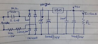
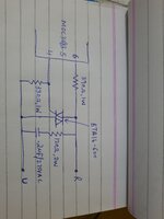
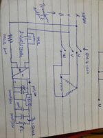
I have made solid relay for 3 phase 90vac motor with capacitive power supply taken from 2 phase of 3 phase 90vac which is input of solid state relay
Vin: 90vac (from transformer 380>90)
IOUT: 50MA @5v

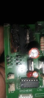
Problem: 1pcb out of 10pcb get capacitor burn or 100ohm 2w resistor burn
Please suggest me what i have to do
 

Attachments

  • 20220302_195629.jpg
    20220302_195629.jpg
    1 MB · Views: 147
  • IMG-20220302-WA0007.jpg
    IMG-20220302-WA0007.jpg
    60.7 KB · Views: 136

Hi,

when the capacitor burns then most likely it is because of overvoltage.

--> use an AC voltmeter and measure the input voltage.
--> compare this value with the specification of the capacitor in it´s datasheet.

The burnt resistor is most likely a consequential fail because of burnt capacitor.

Klaus
 

Ok
Line voltage is 90v phase to phase
But in most of pcb only resistor get burn not capacitor.
I have check by CRO on motor UVW no over voltage seen when motor get off
 

Line voltage is 90v phase to phase
Measured? or expected?

What´s the nominal line frequency?
Is it in a closed box? metal? plastics?
Whats the max ambient temperature?

On 90V and 60Hz the C should limit the current to less than 75mA.
75mA on a 100 Ohms resistor will cause 0.55W of heat. A 1W specified resistor will become very hot, thus i recommend a bigger one.

Klaus
 

Line frequency : 50hz
Metal closed box
Ambient temperature is 30degree
When motor run the drop at 100ohm 2Watt resistor is 5.25v which is expected line current 52mA and power is .275W but resistor is 2W suppose 9 times bigger then continuous power.
And theoretically value of 2.2uf is also near.

Even i am using MOC3083 Triac driver for BTA16A-600

I have not add mov for 150v phase to phase input of power supply does it will solve my problem

And i also thinking to add 1amp 250vac fuse instead of 10ohm 1/2w resistor
 

Hi
I have not add mov for 150v phase to phase input of power supply does it will solve my problem
I guess not. It depends on the hight and duration of the overvoltage signal.

And i also thinking to add 1amp 250vac fuse instead of 10ohm 1/2w resistor
A resistor is no fuse. So a fuse has defined trip characteristic. It should avoid explosion and fire. But it will not keep capacitor and resistor alive.

Klaus
 

It should avoid explosion and fire. But it will not keep capacitor and resistor alive
Yes, but will help to prevent pcb burning during capacitor/ resistor
--- Updated ---

If capacitor is able to problem sufficient current and resistor is able to handle enough heat.
So i am wonder which thing blow capacitor and resistor some time only 100ohm resistor
 

Hi,

as already written:
I see just two rather likely causes for this problem: (there may be other causes)
* too high voltage (maybe temporarily)
* capacitor is not rated for the applied voltage

None of both we (forum) can verify.

Klaus
 

The other factor not mentioned is what the supply is used for. For example, is it possible the negative output is getting connected to earth or one of the other phases, that would connect the resistor and one of the diodes directly across high voltage.

Brian.
 

The other factor not mentioned is what the supply is used for. For example, is it possible the negative output is getting connected to earth or one of the other phases, that would connect the resistor and one of the diodes directly across high voltage.

Brian.
I just using +5v for mcu, IR sensor, proximity sensor, MOC3083 Driver.
I have 90v phase to phase one phase is going to capacitor and another phase to direct bridge via 100ohm 2w resistor.
 

the triac switching puts notches on the mains, these higher frequencies go straight thru the 2.2uF cap and cook the resistor, if there are other noises on the mains from other equipments this will make it worse. this is a well known issue for cap dropper psu's ....
 

the triac switching puts notches on the mains, these higher frequencies go straight thru the 2.2uF cap and cook the resistor, if there are other noises on the mains from other equipments this will make it worse. this is a well known issue for cap dropper psu's ....
But when i check on motor terminal there was no spike during turn on and off i am using zero crossing detected opto triac driver.
Right unexpected energy may be cause of burn
Mov or tvs diode may help in this case ?
 

Hi,

You say there is a transformer in front of it.
What size /watts is it?

When you switch the transformer off while the motor is off (unloaded) then all the energy stored in the transformer may cause high energetic peaks.
Depending at witch time of the sine you switch off.
When measuring with a scope: be careful not to kill your scope.

Klaus
 

But when i check on motor terminal there was no spike during turn on and off i am using zero crossing detected opto triac driver.
Right unexpected energy may be cause of burn
Mov or tvs diode may help in this case

Hi,

You say there is a transformer in front of it.
What size /watts is it?

When you switch the transformer off while the motor is off (unloaded) then all the energy stored in the transformer may cause high energetic peaks.
Depending at witch time of the sine you switch off.
When measuring with a scope: be careful not to kill your scope.

Klaus
Transformer step down 3phase 380v to 90v for motor Iout:5amp @90vac
Zero crossing driver always switch on after zero crossing of sine wave and after switch off triac conduct for following half cycle.
Thats why i choose zero crossing driver instead of random phase triac driver
 

Hi
Transformer step down 3phase 380v to 90v for motor Iout:5amp @90vac
Zero crossing driver always switch on after zero crossing of sine wave and after switch off triac conduct for following half cycle.
Thats why i choose zero crossing driver instead of random phase triac driver
You talk about motor swithiching, but I asked for transformer switching.
Or do you control the transformer with your triac?

Sadly we miss a draft about your circuit.

Klaus
 

Transformer step down 3phase 380v to 90v for motor Iout:5amp @90vac
Zero crossing driver always switch on after zero crossing of sine wave and after switch off triac conduct for following half cycle.
Thats why i choose zero crossing driver instead of random phase triac driver
 

Attachments

  • 20220303_155403.jpg
    20220303_155403.jpg
    1.1 MB · Views: 96
  • 20220303_155414.jpg
    20220303_155414.jpg
    1.2 MB · Views: 92

Status
Not open for further replies.

Similar threads

Part and Inventory Search

Welcome to EDABoard.com

Sponsor

Back
Top