Continue to Site

Welcome to EDAboard.com

Welcome to our site! EDAboard.com is an international Electronics Discussion Forum focused on EDA software, circuits, schematics, books, theory, papers, asic, pld, 8051, DSP, Network, RF, Analog Design, PCB, Service Manuals... and a whole lot more! To participate you need to register. Registration is free. Click here to register now.

Capacitive power supply failure for microcontroller

Status
Not open for further replies.

abc_de

Full Member level 5
Joined
Jan 9, 2014
Messages
243
Helped
11
Reputation
22
Reaction score
11
Trophy points
1,298
Location
Ludhiana ਪੰਜਾਬ
Activity points
2,939
Hello
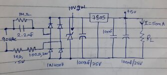
I have made solid relay for 3 phase 90vac motor with capacitive power supply taken from 2 phase of 3 phase 90vac which is input of solid state relay
Vin: 90vac (from transformer 380>90)
IOUT: 50MA @5v

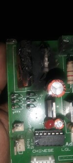
Problem: 1pcb out of 10pcb get capacitor burn or 100ohm 2w resistor burn
Please suggest me what i have to do
 

Attachments

  • 20220302_195629.jpg
    20220302_195629.jpg
    1 MB · Views: 147
  • IMG-20220302-WA0007.jpg
    IMG-20220302-WA0007.jpg
    60.7 KB · Views: 136

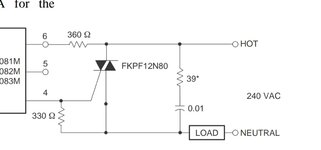
Not necessarily related to capacitive power supply failure, but according to my experience, ZCD triac drivers don't work well with inductive load, e.g. motors.
 

Not necessarily related to capacitive power supply failure, but according to my experience, ZCD triac drivers don't work well with inductive load, e.g. motors.
Any suggestion i just have switch on and off motor maximum motor run time is 8 sec motor off time 2sec nothing else.

I am following suggested circuit in datasheet

BTA16A-600 never below from last 6 month only capacitor and resistor below of psu
 

Attachments

  • Screenshot_20220303-181931_Drive.jpg
    Screenshot_20220303-181931_Drive.jpg
    45 KB · Views: 90
Last edited:

When the solid state relay powering this circuit turns on, the 2.2uF will be fully discharged, and the turn on voltage may be an instantaneous (of up to) 90v x 1.414 = 127 volts.
With only 110 ohms in series the instantaneous power dissipation in those resistors might reach a flash 146 watts.

That is rather a lot for a two watt resistor. The explosive release of heat is going to bring about failure fairly rapidly.

Likewise the 2.2uF capacitor may not be too happy receiving current pulses of over an amp. That may fry the foil, unless its a special pulse rated capacitor, which from the size it obviously is not.

These types of circuits are common in some home appliances, and do work, provided the power is only switched on VERY infrequently, and they are usually left running powered up continuously.

If you are pulsing your motor on and off very frequently, its hardly surprising that the components are failing the way they are. Suggest you redesign the whole thing, because there is no simple way to fix it the way it is now.
 

running powered up continuously
In this board capacitive supply continously on but only switch on/off motor by ZCD traic circuit.

redesign the whole thing
Till now i have add my little experience in hardware design please suggest me any possible change
--- Updated ---

Consider using plain resistor drop. 1 or 1.5 Kohm rated 8W is sufficient. Although inefficient, it never lets through more than 100mA, no matter how you cycle it.
Till now i have add only 100ohm 2w resistor and drop on it is 5v under stand still and running condition circuit thus current passing from resistor is .05A. P=5x.05 > P= .25w which almost 10 times less then wattage of resistor.

When board running everything like 2.2uf/275vac cap, 100ohm,2w resistor, bridge diode, zener diode 10v 2w, 7805 remain cool.

May be during motor on time or off something went wrong. When burning will happen its not sure may be happen after 2days may be never.

What is appropriate why MOV, TVS, capacitor at input, NTC in series.

Even i do not the exact cause of Distruction
 
Last edited:

Replace everything to the left of the diode bridge rectifier with a small transformer to step your 90v down to maybe 8v. That should produce about roughly 9 to 10 volts of dc to power the voltage regulator.
It will solve all of your problems.
 

I
Replace everything to the left of the diode bridge rectifier with a small transformer to step your 90v down to maybe 8v. That should produce about roughly 9 to 10 volts of dc to power the voltage regulator.
It will solve all of your problems.
I know about this solution. But customer need only 3 wire input means only 3 phase 90vac and 3 wire for motor only. Bunch of wires confuse to customer. Thats why i work for low cost bulid in supply.
 

why MOV, TVS, capacitor at input, NTC in series.

This might lead to a strategy of combining a few methods.

Post #23 (Warpspeed) has what appears to be a plausible explanation for your problem. Post #26 offers a transformer as a solution.

My suggestions: Suppose you add a step-down auto-transformer after your capacitive drop and resistive drop? It reduces AC amplitude by shared methods, that is, resistive drop and two kinds of reactive drop.
(An auto-transformer joins the primary and secondary via a common wire. It's cheaper and less bulky than a power transformer.)

With experimentation you may find capacitive drop maintains Ampere level low enough so you can make the core small and Henry value small.

It's not a conventional technique however the concept may work due to your low power requirements. I may be all wet in this regard. My simulation seems to give desired performance with certain values for capacitor value, Henry value, ratio. I want to gain success with a primary below 100mH.

Furthermore I'm uncertain which principle is at work... whether:
* auto-transformer
* bucking transformer
* bandstop filter
* LC resonance through reversed secondary winding resulting in reduced amplitude.
 

Status
Not open for further replies.

Similar threads

Part and Inventory Search

Welcome to EDABoard.com

Sponsor

Back
Top