Continue to Site

Welcome to EDAboard.com

Welcome to our site! EDAboard.com is an international Electronics Discussion Forum focused on EDA software, circuits, schematics, books, theory, papers, asic, pld, 8051, DSP, Network, RF, Analog Design, PCB, Service Manuals... and a whole lot more! To participate you need to register. Registration is free. Click here to register now.

Can someone checkout the attached circuit for me (amplifier)?

Status
Not open for further replies.

scream_er

Member level 5
Joined
Feb 22, 2011
Messages
94
Helped
0
Reputation
0
Reaction score
0
Trophy points
1,286
Activity points
2,028
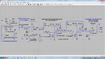
Attached is the circuit which I constructed and tried simulating. I spent hours with it but the simulation doesn't give me the result I want. Can someone check it out and correct it for me if theres any mistake. Its a circuit to filter frequency and then amplifies the voltage to pass to micro-controllers ADC. Basically it has 4 stages, which are:

stage 1: Band pass filter to get frequencies from 700 Hz to 2000 Hz.
stage 2: Amplification with a gain of 14
stage 3: Amplification with a gain of 14
stage 4: Diode to cut off anything above 5V

Circuit: Complete Circuit.png

So, can someone please simulate and correct the mistake for me if there is?
Thanks
 
Last edited:

For one thing, R5 and R7 should be 1k, not 1 ohm. With 1 ohm, each amplification stage is trying to act as a high-pass stage with a low-frequency roll-off at 3.4kHz and a gain of 13001 (~82dB). The open loop gain of an LM358 with a 5V supply is only about 40dB at that frequency.
 

First, how did you calculate dB from gain? Whats the formula. As for 1 ohm, that was a mistake, suppose to be 1k ohm.
 

The basic formula for power ratio in dB is G = 10log10(Po/Pi). Since power is proportional to the square of voltage, voltage gain (amplification) is often expressed as
Av = 20log10(Vo/Vi) dB

This is debatable as power varies as the square of voltage only if the impedance remains the same. Therefore, power gain is the square of the voltage gain only if the input and output impedances are the same. However, expressing voltage gain as 20log10(Vo/Vi) dB is a common (if not unconditionally true) practice. Sometimes the unit dbv or dbvg is used to denote that it's an expression of voltage gain.
 

Hi screamer,

There are lot of points to talk about concerning this circuit.
Let us see them one by one perhaps we can let it do what you want the way you like.

(1) At the input, the capacitor (C2) is rather big (2uF) to drive just an opamp input.
(2) Also at the input, the values of R1 and R2 (113R) are relatively very low to get a virtual ground as 2.5V for the two opamps.
(3) The input linear range of LM358 is -300mV to Vcc-1.4V (5-1.4=3.6). Usually we let the voltage of virtual ground be equal 3.6/2 (1.8V).
(4) It is a good practice to let the equivalent resistance (as R1//R2) of the virtual ground as low as possible. But lowering R1 and R2 will consume a lot of current just to get a reference voltage which is not desirable in practice. The solution is simple. We just add an opamp to act as a buffer (gain +1). In this case the voltage divider (R1 and R2) could be made by relatively high value resistors (above 10K for example) while the buffer output provides a low impedance voltage source (virtual ground in this case) assuming its load will not exceed its rated current limit.

I can't go on since I couldn't relate your requirements with the 60Hz mains voltage (120Vrms).
Why 700Hz and 2000Hz are chosen? Do you try extracting a signal in this frequency band which is added on the mains voltage?
Anyway, and as it was already pointed out by Pjdd, the opamps run as high pass filter (each of gain 14 at high frequencies assuming the opamp is ideal). R3 and C1 form a simple low pass filter (cut-off close to 2000Hz) but R3 should be made larger and C1 lower.

Kerim
 
The circuit was wrong, so it has been edited now. Actually what I want to achieve is to detect a baby when crying and feed the voltage to micro controller to detect the peak voltages. Can you draw me the circuit with the buffer and the correct value of components. I have tried for 2 weeks now.

Thanks
 

And what will you use as an input detector for the baby cry?
This is important in order to know an estimated value of the audio signal level at the input (and to design its hardware).

What is the role of an MCU in this project? Opamp can detect the peak voltage and if used as comparator it can trigger an output load above a certain level. For instance, isn't your project like a light controller by music sound? In my simple product I sell, I use a condenser microphone (2 or 3-wire type) with LM324 IC (as LM358 but quad) which amplifies the audio signal then triggers a triac (electronic AC switch) when the sound level is relatively high (set by a trimmer and actually the board has 3 outputs for bass, medium and treble).

Kerim
 

I use an electret condenser microphone just like you. Actually I am not very good in circuits. So I am gonna use a micro-controller to detect the voltage peaks per defined time. And then pass the baby crying voice through a transmitter to receiver. I just don't know how to implement the first part where I need to pick up the baby voice using electret microphone, filter and amplify. Can you modify for me the circuit I have attached and post it back if you can.

Thanks.
 

I see... tomorrow I will try drawing a possible circuit (since many solutions could exist for the same goal).
I will likely use a trimmer to vary the voltage gain since the microphone sensitivity could vary with type.
I will assume that 700 to 2000Hz is adequate for a baby cry spectrum and the upper and lower limits are not critical (since we will use standard values for the resistors and capacitors).
Finally, since LM358 is supplied by a single voltage 5V there is no need for D1 (the output cannot go lower than ground) and D2 (the output without a pull-up resistor will be limited to Vcc-1.4V, hence 3.6V approximately). Is it ok for your MCU pin to be driven by a signal from 0 to 3.6V, perhaps a bit higher but not more than 4V)?

Kerim
 

My microprocessor is from 0 to 5V. So somewhere around 4.5 would great, so that the resolution will be good when changing from analog to digital. Ok, thanks. It would really help, because I have been struggling for quite sometime now. Let me know when you have the solution. Meanwhile I will try myself learning and learning. Where exactly does the 1.4V comes from?

Thanks.
 

Approximately 1.4V is twice the average Vbe forward voltage (0.7V, silicon NPN transistor). If you look at the datasheet of LM358 (or LM324), there might be a figure showing the internal circuit of the opamp. The positive (high) driver at the output consists of two cascaded NPN transistors hence the factor 2 in the drop voltage 2 * Vbe.
If you like a higher voltage, we can add a pull-up resistor but the lowest voltage will likely increase a little bit due to the increase of the sink current. After all, you can choose later the best value of the pull-up resistor that suits your need (I will assume it 4K7).

Kerim
 
Last edited:

I attached an image of a circuit to start with. Its band pass filter (U2 and U3) is not well flat. It is rather a bit selective with a center frequency close to 1200 Hz (square root of 700 * 2000).

I also attached the circuit LTspice files just in case.

Kerim

Note_1: LM324 is like LM358
Note_2: On my simulator, the output couldn't be higher than 4V so I let Vref (virtual ground) be 2V. If real necessary you may need to find out a rail-to-rail opamp (its output made by MOSFET instead of BJT).
 

Attachments

  • CryDetector_03_asc.png
    CryDetector_03_asc.png
    107.5 KB · Views: 109
  • CryDetector_v3.zip
    3.9 KB · Views: 95

Status
Not open for further replies.

Part and Inventory Search

Welcome to EDABoard.com

Sponsor

Back
Top