Continue to Site

Welcome to EDAboard.com

Welcome to our site! EDAboard.com is an international Electronics Discussion Forum focused on EDA software, circuits, schematics, books, theory, papers, asic, pld, 8051, DSP, Network, RF, Analog Design, PCB, Service Manuals... and a whole lot more! To participate you need to register. Registration is free. Click here to register now.

Can anybody tell me how to understand the following circuit

Status
Not open for further replies.

vvsvv

Full Member level 1
Joined
May 26, 2004
Messages
98
Helped
0
Reputation
0
Reaction score
0
Trophy points
1,286
Activity points
796


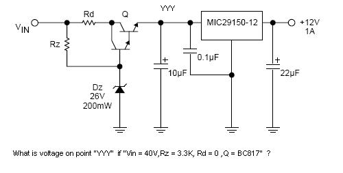
Where Q is a generic NPN transistor, such as BC817 .
So what is the voltage of point "YYY" , if Vin = 40V ?
and what is the voltage of point "YYY" , if Vin = 20V ?

how to understand the circuit ?
when Q isin state of saturation ?

Thanks!!!
 

HI
this as a simple voltage regulator
in two cases, the yyy voltage is
Vz-VBE1-VBE2
VBE1 and VBE2 are darlington BE voltage.
I think it can acts as current limiter too.
regards
 

So , If the vin = 40v , and the vbe1=vbe2=1v,
then, Vyyy = 26-1-1 = 24 V ?

why Vyyy ?= 40-Vce1-Vce2 ???

Thanks.
 

Re: Can anybody tell me how to understand the following circ

The circuit can be thought of as a cascaded regulator. The first stage regulates the voltage to 26V-2*Vbe, while the second regulates it to 12V.

The advantage in general of a cascaded regulator is the better line regulation (smaller changes in output voltages due to changes in input voltages). It is easy to see why: the second regulator sees already a somewhat regulated voltage at its input, so its output changes less than it would otherwise.

However, in some cases this circuit can be used to limit the power dissipation in the second regulator, if the input voltage is too high, because the dissipation in the second regulator is the product of the load current and the input-output voltage diffeerential. Since the input voltage is limited to about 25V, there is only 13V across the regulator. If the first stage was not there, the second regulator would have seen the entire input voltage, thus increasing its dissipation.
The rest of the power is then dissipated by the transistor.

Finally, such a circuit can be used as a clamp, to provide the second regulator with an acceptable input voltage. Suppose it can only accept 30V at the input, but your input voltage is 40V. The circuit shown will "clamp" the input voltage to about 25V, that is, if the input voltage is less than 25V, it will appear at the YYY point, minus 2Vbe. But if it is higher, then the voltage at YYY will stay at 25V, being regulated by the transistors/ Zener circuit.

So this is how the circuit works. One of the reasons above mandated its use: either there was a need for better regulation than the second regulator alone could provide, or the power dissipation was too great for the second regulator to handle, or the input voltage was too high for it.
 

HI
I'm sorry.
this regulator will not work for Vin=20 v correctly.

why Vyyy ?= 40-Vce1-Vce2 ???
because we must choose the path that have deterministic voltages or currents.

regards
 

Status
Not open for further replies.

Similar threads

Part and Inventory Search

Welcome to EDABoard.com

Sponsor

Back
Top