Garyl
Full Member level 5
Hey,
I have stumbled upon the VK3AJG while searching for some simple radio stuff to build. I am a very beginner in this field, so I'd like to ask for your opinion about this project.
This transmitter is using only transistors (BC549C, BC547C, BC557B, 2N2219), no ICs.
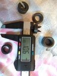
The project is described here:
**broken link removed**
The description says:
Schematic mirror:
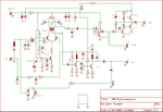
Eagle files mirror:
View attachment eagle_DSB-Minitransceiver.zip
PDF board mirror:
View attachment DSB-Minitransceiver.pdf
I have following questions:
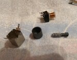
1. Coil L7 is 14 turns on old 10mm 455Khz IF Can. - what is that and where to get that? I have found a few such "cans" in my old electronic parts, but I don't know how to check what's the frequency of those "cans".
2. The receiver is quite sensitive and tunes about 80-90Khz, tx output is ~300-500mW - what does it exacly mean? What will I be able to receive? How far will I be able to communicate if I make two exact transreceivers and tune them to the same frequency?
3. Can this project work in "walkie-talkie mode", I mean, powered by battery and with very small, moveable antenna? Or do I need a large antenna for that?
4. Why does Q4 3.58Mhz ceramic resonator must be ceramic?
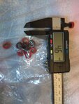
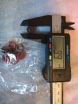
5. Ferrite beads for L1 and L6 can be any from old equipment?
6. What kind of wire do I use for the coils? It's not specified in the description
7. Do I have to connect somehow the "top ground layer" to the bottom layer ground?
8. What kind of speaker and mic is here needed? 8Ohm speaker is ok?
9. If it's "80m" then why description says 80-90kHz? I tought it should be 4000kHz or so
I have stumbled upon the VK3AJG while searching for some simple radio stuff to build. I am a very beginner in this field, so I'd like to ask for your opinion about this project.
This transmitter is using only transistors (BC549C, BC547C, BC557B, 2N2219), no ICs.
The project is described here:
**broken link removed**
The description says:
A Simple 80 Metre DSB Minitransceiver
VK3AJG
The receiver is quite sensitive and tunes about 80-90Khz, tx output is ~300-500mW
C26 is small plastic tuning capacitor (100pf)
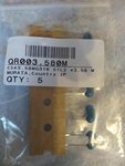
Q4 is 3.58Mhz ceramic resonator.
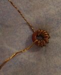
Coil L1 is 10 turns trifilar wound on ferrite bead.
Coil L6 is 10 turns bifilar wound on ferrite bead.
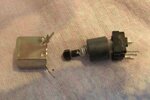
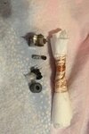
Coil L7 is 14 turns on old 10mm 455Khz IF Can.
All other coils are RF chokes.
Tx/Rx switching is done with a DPDT switch connected to
JP3 and JP5.
Adjust preset pots for best carrier balance on tx, and tune
L7 for best reception.
NOTE: Must use double sided pc board, with the top layer as a ground plane,
using single sided board the receiver will not work very well.
Schematic mirror:

Eagle files mirror:
View attachment eagle_DSB-Minitransceiver.zip
PDF board mirror:
View attachment DSB-Minitransceiver.pdf
I have following questions:
1. Coil L7 is 14 turns on old 10mm 455Khz IF Can. - what is that and where to get that? I have found a few such "cans" in my old electronic parts, but I don't know how to check what's the frequency of those "cans".
2. The receiver is quite sensitive and tunes about 80-90Khz, tx output is ~300-500mW - what does it exacly mean? What will I be able to receive? How far will I be able to communicate if I make two exact transreceivers and tune them to the same frequency?
3. Can this project work in "walkie-talkie mode", I mean, powered by battery and with very small, moveable antenna? Or do I need a large antenna for that?
4. Why does Q4 3.58Mhz ceramic resonator must be ceramic?
5. Ferrite beads for L1 and L6 can be any from old equipment?
6. What kind of wire do I use for the coils? It's not specified in the description
7. Do I have to connect somehow the "top ground layer" to the bottom layer ground?
8. What kind of speaker and mic is here needed? 8Ohm speaker is ok?
9. If it's "80m" then why description says 80-90kHz? I tought it should be 4000kHz or so
