Schema inc.
Newbie level 5
- Joined
- Mar 7, 2013
- Messages
- 8
- Helped
- 0
- Reputation
- 0
- Reaction score
- 0
- Trophy points
- 1,281
- Location
- Vic, Australia
- Activity points
- 1,339
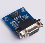
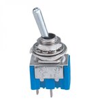
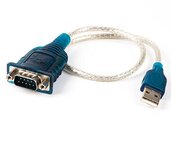
Hi, everyone i would like to know how to approach in building a electronic circuit that will use a volume type/Power ON/OFF /Pull test switch to power on the Unit also 4 toggles 1st toggle is ch A(on) 121.70 or (on)B 121.90 Preselected fixed frequency and the 3 Frequency select toggles are mom(on) off(centre) mom(on) f rom R to L --3rd from right incr or decr last digit of (000.0X), 2nd from R incr or decr middle digit (000.X0), far Left toggle incr or decr (00X.00) and i would like to use a pic16F628A microchip/s to control the whole thing, also I want to be able to interface to flight sim via TTL to rs232 (USB)?
---------------------------------------------------------------------------------------------------
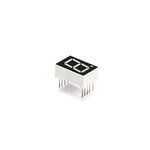
I would like to use 5 npn/pnp transistors with 5 digit 7 Seg displays CA or CC : whichever /whatever gives me the max brightness. also I would like to use discrete components as much as possible: to keep costs down.
and all 5 Digits must be lit AT ONCE WHEN, POWERED ON.
----------------------------------------------------------------------------------------------------------------
If anyone would like to give me a step explanation in the design, that will be great. I have tried researching a lot on all this and cannot find a complete tutorial so to speak on step instructions. I really want to learn how this is programmed and interfaced.
Input power: 12DC
[X= digit being changed]
---------------------------------------------------------------------------------------------------
I would like to use 5 npn/pnp transistors with 5 digit 7 Seg displays CA or CC : whichever /whatever gives me the max brightness. also I would like to use discrete components as much as possible: to keep costs down.
and all 5 Digits must be lit AT ONCE WHEN, POWERED ON.
----------------------------------------------------------------------------------------------------------------
If anyone would like to give me a step explanation in the design, that will be great. I have tried researching a lot on all this and cannot find a complete tutorial so to speak on step instructions. I really want to learn how this is programmed and interfaced.
Input power: 12DC
[X= digit being changed]
Last edited: