Continue to Site

Welcome to EDAboard.com

Welcome to our site! EDAboard.com is an international Electronics Discussion Forum focused on EDA software, circuits, schematics, books, theory, papers, asic, pld, 8051, DSP, Network, RF, Analog Design, PCB, Service Manuals... and a whole lot more! To participate you need to register. Registration is free. Click here to register now.

7 segment display connections

Status
Not open for further replies.

pgr2002

Member level 5
Joined
Aug 1, 2013
Messages
87
Helped
0
Reputation
0
Reaction score
0
Trophy points
1,286
Location
Hyderabad, India
Activity points
2,015
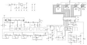
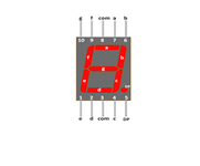
I am attaching one circuit diagram of ESR digital meter using ICL7107. Here in this circuit the 7 segment display, 10th position is shown as "f", but actually the 10th position is "g". Which is correct. (7 segment display is common anode). Will anyone clarify regarding this and which one is correct.
Pin "9" is also interchanged in circuit diagram and the rest of the pins match.
 

Attachments

  • Circuit Diagram.png
    Circuit Diagram.png
    785.3 KB · Views: 195
  • 7 seg display pins.png
    7 seg display pins.png
    23.5 KB · Views: 194

Hi,

There may be differnt displays aournd with differnt pinning.

Thus the only "safe" way is to find the partnumber (usually printed on it) and read the datasheet.
Everything else is guessing and may be false.

Klaus
 

The schematic has f and g connections to 7107 swapped on all 3 digits,
LD1 - LD3.

Regards, Dana.
 

The connections are not swapped, the display symbol has a typo, f/g letters swapped.

Can I assume that the digits 9 & 10 instead of g & f and proceed accordingly
--- Updated ---

Hi,

There may be differnt displays aournd with differnt pinning.

Thus the only "safe" way is to find the partnumber (usually printed on it) and read the datasheet.
Everything else is guessing and may be false.

Klaus

The part number that I have is HDSP5501 HILITE and this segment has what I had previously attached the 7 segment display file.
And the letters concerning f & g is in the same position as in the file, but letters differ
 

Of course you could always just try it and see. A very simple test rig (power source, resistor and a couple of wires) will tell you in seconds.
However I'd go by the data sheet.
Susan
 

Hi,

There may be differnt displays aournd with differnt pinning.

Thus the only "safe" way is to find the partnumber (usually printed on it) and read the datasheet.
Everything else is guessing and may be false.

Klaus

Thanks a lot. I just completed the meter with veroboard. The variable resistor in the schematic is 25k. I could not get this but I had 20k.
At the time of calibration R21 i.e. 1K is preset to 0.00 when both the test leads are connected. Upto this it is ok. But when we connect
18 ohms between the leads and adjust R25 (25k) (20k is used) it is not showing and adjusting to 18 ohms but gives more than 53 ohms.
Is it due to this 20k. But when I check with good caps it is showing 0.00 or 0.01 or 0.02 but not further. please clarify.
 

Hi,

I am not surprised that a veroboard design gives wrong reading.
I guess you don´t use a proper GND plane ... and without GND it is more difficult to get it working accurately.

We maybe can give you some wiring hints when you show us your veroboard.

Klaus
 

Hi,

I am not surprised that a veroboard design gives wrong reading.
I guess you don´t use a proper GND plane ... and without GND it is more difficult to get it working accurately.

We maybe can give you some wiring hints when you show us your veroboard.

Klaus

please see the attached image
 

Attachments

  • vero board.png
    vero board.png
    143.4 KB · Views: 148

Not clear how you are adjusting a capacitance meter with a reference resistor. May be you are referring to design documents not yet undisclosed in this thread. Without giving all related information, the question leads nowhere.
 

Not clear how you are adjusting a capacitance meter with a reference resistor. May be you are referring to design documents not yet undisclosed in this thread. Without giving all related information, the question leads nowhere.

I am attaching all the relevant files for reference
 

Attachments

  • ESR Meter Digital with IC L7107.pdf
    4.1 MB · Views: 189

Hi,

I am not surprised that a veroboard design gives wrong reading.
I guess you don´t use a proper GND plane ... and without GND it is more difficult to get it working accurately.

We maybe can give you some wiring hints when you show us your veroboard.

Klaus

I attach here the veroboard and also the description of adjusting the variable resistors.
 

Attachments

  • Circuit Diagram.png
    Circuit Diagram.png
    785.3 KB · Views: 140
  • ESR Meter Digital with IC L7107.pdf
    4.1 MB · Views: 269
  • vero board.png
    vero board.png
    143.4 KB · Views: 142

Hi,

4th page:
Note: The layout is the one with the copper surface, the solder side.
I guess this means that the soldering side is a GND plane. Not sure.

Let´s imagine you don´t know about the wiring.... could you tell from the tiny picture you gave us - and only one side - which part is connected to which other part ...and how?

Often on can see from the documentation whether a design is good or not. It´s clearly a hobbyist´s project. Using a two wire measurement method for ESR down to 10 mOhms is more than optimistic.
--> better try to get the original ELV description.

Or even better: go through some (professional) application notes provided by semiconductor manufacturers.

Klaus
 

Hi,

4th page:

I guess this means that the soldering side is a GND plane. Not sure.

Let´s imagine you don´t know about the wiring.... could you tell from the tiny picture you gave us - and only one side - which part is connected to which other part ...and how?

Often on can see from the documentation whether a design is good or not. It´s clearly a hobbyist´s project. Using a two wire measurement method for ESR down to 10 mOhms is more than optimistic.
--> better try to get the original ELV description.

Or even better: go through some (professional) application notes provided by semiconductor manufacturers.

Klaus

I connected the other side of copper plate as per the diagram. I rechecked 2-3 times and corrected them and the final layout is as per the
attached file. As per the instructions I could not zero in while adjusting R21 (1k preset). On power on it shows as per 4 segment displays -
1, blank, dot, blank, blank.

On connecting the two testing terminals it shows blank, dot, one, eight. (maximum adjustments)
On connecting the 18 ohms resistor between the two testing terminals it shows blank, four & dot, eight, three.

Is it workable or should I discard it / ignore this project.
 

Attachments

  • veroboard copper side.JPG
    veroboard copper side.JPG
    460.2 KB · Views: 145

Hi,

this surely does not work like a GND plane.

What also worries me: In the original design I see about 25 resistors. I miss them on your board.

Discard or not:
I´d say you need a good portion of luck to get it reliably working.
And it´s hard to debug it for someone who did not do the exact circuit on his own.

Klaus

There are 24 resistors on the front panel and one resistor on the copper clad side.
 

Hi pgr2002,

Suggestion with through-hole pcbs:
1) Draw/print the layout for the circuit the right way up.
2) Draw/print a mirror image version of it upside-down and with the pins and passive components labelled.
3) Print a spare version of 2).
4) Draw all wiring connections and solder points on 2) with a light, different-coloured ink.
5) Later, each time you solder a few connections, draw over what has been soldered/completed in a darker ink.

Mistakes are easy to make.

If you're familiar with the 7107, think of what you can check (buffered by a reasonable quality op amp) like is osc frequency correct, is Vref correct, and so on. Klaus might remember some other useful trouble-shooting steps with that kind of ADC, he's far more knowledgeable than I'll ever be.

If you're not yet very familiar with the 7106/7107 ADC, there are several application notes about it (I'll upload a couple in a day or so, when I next can) and assorted datasheets and circuit designs based around it that you might not have read but should.

Discard or not? Depends on money-willingless, effort-worthiness, certainty version 1 has multiple issues, willingness to de-solder (and prematurely age them with three waves of heat in total or have to replace) assorted components. You may want to troubleshoot version 1 a bit (i.e. poke around a bit with a buffered DMM and a buffered oscilloscope probe) just in case it provides useful insight about mistakes not to repeat and things that are right that should be repeated, and then do a new version 2.

Not sure if it fits a capacitor esr circuit, but preferable is four-wire measurement system if it can, surely?, and certainly subtracting lead and connector resistance, as mentioned above.

Use a star ground on through-hole circuits, and fussy people might make all ground leads the same length.

My most humble and well-intentioned and friendly opinion, learnt from experiences (plural!), to measure requires removing the minefield of obstacles that will produce more or less inaccurate results; an ADC is a fussy, prissy circuit, your design looks done nicely with effort, but due to normal and habitual inexperience, it looks like it misses that nuance of ADC, etc., circuits - what look like single-turn potentiometers (calculate what e.g. a 10% turn means in voltage or resistance and if that is accurate enough for it's purpose in-circuit) and electrolytic capacitors, the way of measuring the DUT tell me an awful lot...

Also, even with 7-segment display datasheets, check each segment first (before soldering anything) with a suitable resistor to be certain where A is, all the way to G.

You might find you can salvage that circuit by reading up on the 7107 and forum threads about it not working - only because you might recognize similar symptoms to your circuit (or not, but it wouldn't hurt), as well as doing your own trouble-shooting measurements (plan that in advance: a little table with a column for expected results, and a column of your actual measured results for three or four different resistances or capacitors, so as to compare in a calm, ordered, methodical fashion) and hopefully limit 'confusion, anger, frustration' (abundantly free in electronics, as most know) and the 'de-solder, re-solder' to a couple of parts.
 
Last edited:

Thanks a lot for all the replies I got from all. My only doubt is : there are 2 variable resistors in the circuit, values of which are 1K and 25K. I could not get a preset / pot for 25k. I used 20k preset instead of 25k. Will this VR of 20K make a difference in not zeroing the display and also not adjusting to 18 ohms.
 

Status
Not open for further replies.

Part and Inventory Search

Welcome to EDABoard.com

Sponsor

Back
Top