Continue to Site

Welcome to EDAboard.com

Welcome to our site! EDAboard.com is an international Electronics Discussion Forum focused on EDA software, circuits, schematics, books, theory, papers, asic, pld, 8051, DSP, Network, RF, Analog Design, PCB, Service Manuals... and a whole lot more! To participate you need to register. Registration is free. Click here to register now.

Boost converter efficiency calculation in PWM control mode

Status
Not open for further replies.

Safiya

Junior Member level 2
Joined
Oct 25, 2013
Messages
22
Helped
1
Reputation
2
Reaction score
1
Trophy points
3
Visit site
Activity points
0
Hi, Everyone,
I have designed simple boost converter, with
Vi=1.8v
vo=5v
Io= 60mA
ΔIL = 167mA (1.37A to 1.544 A)
Isw= 1.4A (0 to 1.4A spikes)
L=1u
fs= 1M

Could some one please guide me to rough estimate of Efficiency ?
does the ΔIL variation from 1.3A to 1.5A is normal or it must be reduced ?

-Thanks
Safiya
 

Hi,

I think your values don´t match. What is the duty cycle?

Klaus
 

hi,
I need the values as function of Duty cycle if possible.
otherwise suppose a duty ratio of 70%.
thanks
 

Hi,

Confusing...
i don't think one can calculate efficiency this way. With varying duty cycle the currents may also vary.
And efficiency depends on switch rds_on, switching loss, inductance r_dc, inductance core loss, and catch diode loss - mainly.

The best way to get a chart of efficiency is:
* to work with different lod resistances
* calculate Pout = Vout x Iout
* calculate Pin = Vin x Iin
* calculate efficiency = Pout / Pin

Mind: current measurement may cause voltage drop = error

Hope this helps
Klaus
 

Thanks KausST,
I dont mean varying Duty cycle , i can fix it to 70%. and want to calculate efficiency.
i am confused that if i calculate , efficiency using diff loads as u mentioned i can get diff output currents. as you mentioned.
but where to put rds_on , r_dc, if i use this formulae
Pout = Vout x Iout
Pin = Vin x Iin
efficiency = Pout / Pin
Secondly , please check whether this inductor current (1.37A to 1.544 A ) is normal or it should be reduced to increase efficiency.

Regards
 

Hi,

sorry, maybe i´ve confused you.

so now step by step: you want efficiency calculation:
* efficiency is defined as P_out/P_in

with your given data i can calculate P_out, but not P_in
So i tried to simulate your circuit with the given data. But i can´t find a situation that matches your values. (this is what not matches)

Also i tried to calculate the internal power loss. But for that rdson, diode voltage, rdc and so on are missing. So its not possible for me with the given data.

In post#1 you say Io (Output current?) is 60mA. In post#3 you like efficiency as a function of duty cycle. Otherwise i can "suppose" it to 70%.
Because the ouput current surely depends on duty cycle y one can not "suppose" it. (this is what not matches)
On the other hand you can not have varying duty cycle with a constant Io of 60 mA. (this is what not matches)

--> so my solution (to avoid a lot of calculations with rdson, duty cycle...) is to just measure the input current.
With that you have Vi, Ii, Vo, Io, and that is enough to calculate P_in and P_out and in the next step efficiency.

Hope this helped to clarify.
Klaus
 
  • Like
Reactions: Safiya

    Safiya

    Points: 2
    Helpful Answer Positive Rating
Ya,
I have inductor ripple current ΔiL, as (1.3A to 1.5A), because at input of dc-dc boost converter.
in my thinking input current is same as iL rms , (where iL : induct current )
Iin = iLrms = 1.44A
so i calculated the
η = 5*60mA / (1.8*1.44) = 11.5 %

Is this way is right ?
 

Hi,

you are right, yes i see that Iin = IL.

With that you get 11.5% of efficiency, this is a very bad value for a boost converter.
This may be correct or not.

LT devices may work with over 85%. Tiny, SMD...

If you find the 11.5% aor not true then you can try something:
With the given values you may have 2.3W of heating. Small devices will be very hot with that.
With a carful touch you can find wich device is the hottest.

If no device is that hot (then the calculation may be wrong) you can measure with an oscilloscope of your converter is continously switching or works in a burst mode.

Cu
Klaus
 
  • Like
Reactions: Safiya

    Safiya

    Points: 2
    Helpful Answer Positive Rating
Efficiency is lower with a boost converter, compared to a buck converter. Power is lost for 70% of the time (since we are talking about 70% duty cycle).

The load (output stage) utilizes only 30% of the waveform.

So it may be that 11.5% efficiency is the correct figure.

A boost converter is like a pole vaulter. He runs at first, building up speed, in hopes that when he plants the pole, his horizontal speed will translate into vertical distance. This process occurs each cycle.

The horizontal run (input) is separate from the jump (output).

In addition you are in continuous conduction mode. Efficiency will be better in discontinuous mode (although this is not to say you must not use continuous mode).
 
  • Like
Reactions: Safiya

    Safiya

    Points: 2
    Helpful Answer Positive Rating
Hi,

out of curiosity i just looked at www.linear.com.
Search: Boost converter: Vin 1.7..1.8V, Vout 5V, Iout 0.06A,
in the list i picked the firs one with switch current > 1A

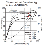
It was the LT
eff.PNG
in the datasheed i found a chart that fits the OP´s data.
I marked the interesting area.
The efficiency is more than 80% - OK, the synchronous mode lowers the loss of a conventional catch diode.

there may be other IC from different manufacturers with different efficiency and of course differen price...

so i was not too bad with my 85% estimation....

Hope this helps.

BTW: at the LT site you may find a lot of information and application notes about power converters.

Klaus
 
  • Like
Reactions: Safiya

    Safiya

    Points: 2
    Helpful Answer Positive Rating
Status
Not open for further replies.

Similar threads

Part and Inventory Search

Welcome to EDABoard.com

Sponsor

Back
Top