Continue to Site

Welcome to EDAboard.com

Welcome to our site! EDAboard.com is an international Electronics Discussion Forum focused on EDA software, circuits, schematics, books, theory, papers, asic, pld, 8051, DSP, Network, RF, Analog Design, PCB, Service Manuals... and a whole lot more! To participate you need to register. Registration is free. Click here to register now.

Boost PWM from <3,3V to 3,3V or 5V

gs1

Newbie
Joined
Oct 24, 2023
Messages
4
Helped
0
Reputation
0
Reaction score
0
Trophy points
1
Activity points
70
Hello,
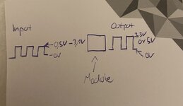
I want to boost a PWM Signal thats less than 3,3V to 3,3V or 5V. I want to be able to decide with a switch whether I have 3,3 or 5V at the output. In addition, an LED should be lit if there is a signal at the entrance. The LED should not draw the energy from the signal.

I've attached a circuit how it might work. I would realize the 9V via a battery. I haven't calculated the values of the resistors yet.

Do you think this design will work? Or do you have a suggestion for a smarter design?


Unfortunately, I can't insert the circuit as a picture. That's why the link:

https://www.falstad.com/circuit/cir...Dq5MMeNByQeNPbwR3IRWAO4EC1l3ZBxAfc-HwG4eWfdAA

1698144989454.png


I really hope someone can help me. Thanks in advance :)
 
Last edited by a moderator:
I do not see where you are switching the adjustable reg V set R's to gen
the alternate V ?

Something like this (only 1 transistor needed) :

1698148746081.png


I would use something like 2N7000 MOSFET to do it to minimize offset
error a bipolar NPN would give you.

So set R4 to produce 5V, and the added R, in parallel with R4, to produce 3.3. Note
high into mosfet = low Vout of regulator

1698149947899.png


Note I did not add all the protective stuff like caps, diode, LM317 should have :

1698150072150.png


Lastly you should worst case the R values to make sure you get the target V's with tolerance goals.

Regards, Dana.
 
Last edited:
The simple falstad simulator circuit seems to assume a mechanical switch for voltage selection.

I see nevertheless some issues.
- Guess you don't want inverting operation of the "boost" circuit?
- Optocoupler diode brings a large voltage drop (about 1.3 V), increasing the minimal input voltage considerably. LED circuit can be better connected parallel to 1k output resistor, saving the opto-coupler.
- Need to know the effective output load. Is 1 k pull-up resistor sourcing sufficient current?
 
Hi,

there are a lot of issues:

A PWM signal has two states: HIGH and LOW.
You may define LOW = <0.6V and HIGH >2.0V
"Less than 3.3V" is not a good definition.
(it´s important to define what you mean, there are a lot of threads in this forum that decide the PWM voltage as the average voltage .. involving duty cycle)

What is the box "in out adj" exactly?

The LED should not draw the energy from the signal.
But it does. In your schematic.
The problem is that you are focussed on the red circle device, but ignore that inside the optocoupler there also is a LED.
And with optocouplers with an CTR<100 your circuit is counter productive. It draws more current from the input than your red circle LED draws.
You need to give details on this

What´s the expected output current and the expected output voltage precision?
As soon as you dtaw some output current the signal will drop, too.

***
A much simpler, more perfect solution could be (depending on your requirements) to use a logic level controlled CMOS ANALOG SWITCH.
It draws way less power supply current, less signal current, you may drive LED and output independently, you get less output resistance ....

***

Before you ask for a schematic: please give a most detailed list of your requirements.

Klaus
 
I added a small cap on the Vref pin to mitigate a problem with transient performance.

Note this is with effective PWM rate of 1 Khz.

1698152675759.png


Regards, Dana.
 
I added a small cap on the Vref pin to mitigate a problem with transient performance.

Note this is with effective PWM rate of 1 Khz.

View attachment 185724


Regards, Dana.
Hello Dana,
Thank you very much for the detailed help.
I have recreated the circuit you proposed and it seems to me that the circuit produces a constant DC voltage of 3. 3 volts.
But I would like to amplify the rectangle signal or PWM.

If I'm wrong I'm sorry I'm quite new to the world of electronics and therefore I don't know so much yet.

Thanks again and maybe you can help me further
Kind Regards
 
Hi,

there are a lot of issues:

A PWM signal has two states: HIGH and LOW.
You may define LOW = <0.6V and HIGH >2.0V
"Less than 3.3V" is not a good definition.
(it´s important to define what you mean, there are a lot of threads in this forum that decide the PWM voltage as the average voltage .. involving duty cycle)

What is the box "in out adj" exactly?


But it does. In your schematic.
The problem is that you are focussed on the red circle device, but ignore that inside the optocoupler there also is a LED.
And with optocouplers with an CTR<100 your circuit is counter productive. It draws more current from the input than your red circle LED draws.
You need to give details on this

What´s the expected output current and the expected output voltage precision?
As soon as you dtaw some output current the signal will drop, too.

***
A much simpler, more perfect solution could be (depending on your requirements) to use a logic level controlled CMOS ANALOG SWITCH.
It draws way less power supply current, less signal current, you may drive LED and output independently, you get less output resistance ....

***

Before you ask for a schematic: please give a most detailed list of your requirements.

Klaus
Hello Klaus,
I'm sorry if I didn't describe my problem accurately enough I haven't been in electronics for so long and therefore my knowledge is not very good yet. Thank you so much for your help!

I try to describe my requirements more precisely:
I should be able to amplify a rectangle signal or a PWM that has a high level lower than 3. 3V and a low level of 0V to a high level of 3. 3V and to 5V. One application case would be to increase the signal of a sensor so that it can be processed by an Arduino.
In addition, a high signal should be illuminated by an LED, which does not derive its energy from the input signal. That in the optocoupler a diode is installed I have not noticed :/

I hope I could represent my requirements a little better.

Thank you again.
Kind Regards
 
Hi,

I wrote: "Less than 3.3V" is not a good definition.
Now you write: "that has a high level lower than 3. 3V"

do you agree that
* 3.299V
* 1.50V
* 0.1V
* 0V
* -1V
* -200V
all are lower than 3.3V?
So according your requirement this all are considered "HIGH".
I doubt you want this.

****
From your new description I geuss what you need is a level converter.
* from 3.3V LVCMOS levels --> 5V CMOS levels
Correct me if I´m wrong.

But still I´m not sure why you need a switch for selecting 3.3V and 5V.
You need to explain.
****
(You could do an internet search for it. You are not the first one with this problem)
If I need a level converter from 3V3 logic to 5V logic, I usually use a 74HCTxx device. Any non inverting will do.
Power it with 5V. And it is happy with 3.3V input levels. Cheap, best availability, singe gate, multiple gates, fast, reliable, valid output levels....

also possible solution:
MAX4544 (or any other suitable analog switch)
GND = GND, V+ = 5V, IN = Input, NC = GND, NO = 5V, COM = output

****
Btw:
I find the word "amplify" a bit misleading.
It is used in the analog world with a (fixed) gain.
Example: Gain = 1.5
input --> output
0 --> 0V
0.1V --> 0.15V
0.3V --> 0.45V
0.5V --> 0.75V
2.0V --> 3.0V
3.0V --> 4.5V

but I guess you rather want this:
0 --> 0V (LOW)
0.1V --> 0V (LOW)
0.3V --> 0V (LOW)
0.5V --> 0V (LOW)
2.0V --> 4.5V (HIGH)
3.0V --> 4.5V (HIGH)

***
Arduino ... is a name for an IDE and a is company name. But it describes no hardware.
You may use "Arduino UNO" --> this describes a hardware. We can find datasheets / descriptions for this hardware.
There is Arduino hardware running with 3.3V and other Arduino hardware running with 5V.

***
The "LED" in the optocoupler is clearly depicted in your schematic and described in every datasheet. You don´t want to read this: but you need to learn to read datasheets. We professionals do this all day .. and this is where we have our knowledge from.

***
Your indicator LED may be driven by the logic IC, by a MOSFET, by a BJT ... use what you have by hand. Don´t forget the resistor.

Klaus
 
Hello Klaus,
thank you very much for your efforts to help me. The module I should create should simply “amplify” (I don’t know how do call it correctly) the input signal to 3.3V or 5V so that it can be used by different Arduino hardware. I received this requirement from the university. I have attached a sketch to clarify what I mean. What speaks against amplification using a transistor?

Best regards
 

Attachments

  • IMG_4137.jpeg
    IMG_4137.jpeg
    1 MB · Views: 42
“amplify” (I don’t know how do call it correctly)
My bad, I should have written that it´s not an amplifier but a level converter .....
(I have a deja vu...)

so that it can be used by different Arduino hardware
Thanks for this very specific information....
Did you read my post before?

What speaks against amplification using a transistor?
1) you asked for a smarter solution.
2) non inverting
3) faster switching
4) more symmetrical switching
5) less power consumption
6) less input current draw
7) better voltage levels
8) lower output impedance --> more stable levels
9) symmetric output impedance
10) less components
11) smaller
...

Now I leave place for others to help you.

Good luck

Klaus
 
Klaus is teaching you that you need to specify all your assumptions with values and functions. This should be done before you try to design it.
  1. Regulators all use some stable reference for Feedback (FB) so the output voltage is defined by some ratio relative to 0V to match FB.
  2. This Linear Reg ADJ box (like LM317) uses a fixed voltage reference between Out and Adj. It is not a PWM circuit but rather a linear one.
  3. Your signal lacks parameters for a function, such as isolated, peak detected, logic level, voltage control, and some transfer functions.
  4. The IR LED and Indicator Red LED could share the same current unless it has some other function.
  5. Perhaps you are thinking of a level shifter on the interface.
 

LaTeX Commands Quick-Menu:

Part and Inventory Search

Welcome to EDABoard.com

Sponsor

Back
Top