Continue to Site

Welcome to EDAboard.com

Welcome to our site! EDAboard.com is an international Electronics Discussion Forum focused on EDA software, circuits, schematics, books, theory, papers, asic, pld, 8051, DSP, Network, RF, Analog Design, PCB, Service Manuals... and a whole lot more! To participate you need to register. Registration is free. Click here to register now.

Board-fabrication question re: row of holes to create a slot

Status
Not open for further replies.

Electrojim

Newbie
Joined
Aug 20, 2012
Messages
2
Helped
0
Reputation
0
Reaction score
0
Trophy points
1,281
Location
Orange County, California
Activity points
1,309
I'm using an older, somewhat bonehead PCB layout program that has no obvious means of calling out slots, only round holes in pads. I need a slot to accommodate flat tabs from a connector. Slots will hold the connector in place as it goes over the wave, large round holes don't. What does a PCB drill do when it comes down at the edge of another hole? Does it enlarge the hole or does it wander?

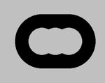
I've attached a screenshot of the 'board layer' or 'multilayer' view of an obround pad with three holes. The pad has its own 40-mil hole in the center, then there are two 41-mil pads with 40-mil holes drilled right at the left and right edges of the center hole. Will this work? Any help here is much appreciated.
 

Attachments

  • Snap4.jpg
    Snap4.jpg
    15.6 KB · Views: 101

Hi,

Best you can do: ask the manufacturer.

Klaus
 

Hi,

how are you defining your board outline? Maybe that approach might be used to create a slot.

BR
 

Generally the manufacturer will recognise that your trying to make a slot and use a router bit in that position.

You could always draw it as the correct size/width line on a separate layer and call it "slots" as a Gerber, identify plated/non plated slots by different layers/files.
 

Overlapping drill hits is a great way to break drill bits and make your fabhouse hate you. Many won't accept such designs.

Not sure which "bonehead" software you're referring to, but in general defining slots can be done in the same manner as defining any other feature on the layout (assuming you're exporting to gerber files):
1. Make a layer in your artwork. Call it something random like "routing"
2. Draw the shape of the routed feature you want.
3. When exporting the gerbers for your design, export the "routing" layer to its own gerber file. Put "routing" somewhere in the file name.
4. When organizing your deliverables for the fabhouse, you should have a top level readme file which lists each file, and describes its content. Make sure this file mentions that you have internal routes (make sure it's clear which ones are plated or non plated), and point out your routing gerber.
5. The fabhouse will looks at the files and figure out how to best create the features (tool size, tool path, etc). They definitely won't use a row of drill hits.
 

Status
Not open for further replies.

Part and Inventory Search

Welcome to EDABoard.com

Sponsor

Back
Top