Continue to Site

Welcome to EDAboard.com

Welcome to our site! EDAboard.com is an international Electronics Discussion Forum focused on EDA software, circuits, schematics, books, theory, papers, asic, pld, 8051, DSP, Network, RF, Analog Design, PCB, Service Manuals... and a whole lot more! To participate you need to register. Registration is free. Click here to register now.

[SOLVED] beginners question re: light meter circuit

Status
Not open for further replies.

ASelis

Newbie level 3
Joined
May 6, 2012
Messages
3
Helped
0
Reputation
0
Reaction score
0
Trophy points
1,281
Location
Palo Alto, CA
Activity points
1,301
Just started doing hobbyist projects in the last month--building simple circuits--and had a question about this design for an analog light meter:
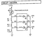
001.jpg

As light / voltage flowing through the photoresistor increases, it lights LED 1, then 2...
Why does the circuit connect to ground at two points, and how does R3 set a threshold point for successive LEDs to light?

I know this is a simple question--Thanks in advance for replies.

A
 

Because, simplified saying - a LED will stop the voltage to increase at a given voltage.

Much loke the way a zener diode would. Just think about where the current will go when voltage over the first led can't get above t.ex 2 volts.
 

Thanks--I understand how the voltage cascades down to additional LEDs, but still can't get my head around how R3 helps.
 

This is a nice and simple circuit but for it to work properly, the LEDs and the remained resistor values may need to be considered in the analysis.

As a start... which LED will light first?
I guess you will say D1.
Well, this is right because it has the highest voltage (on R1+R2+R3).
Then it comes the turn of D2 (on R2+R3) then D3 (on R3).

As we saw, R3 is common to all. Increasing or decreasing it will affect the voltages on all LEDs.
 
  • Like
Reactions: ASelis

    ASelis

    Points: 2
    Helpful Answer Positive Rating
Thanks (and Shukran), Kerim.
I guess the specific question was why I would need to ground the circuit through R3.
 

why I would need to ground the circuit through R3
Oh sorry... I see now what you mean.
Let us assume R3 is removed... what would happen?

To be honest, the complete answer needs that we have all values. But in any case LED1 will start to turn on as the LDR resistance starts decreasing to provide enough current for the LED light to be seen.
 
Last edited:

By connecting R3 to ground, it sets up a totem of volt levels at which the led's turn on. Decreasing R3 will decrease current through the bottom 2 led's, thus increasing the volt level needed to turn on those led's.

I suggest getting familiar with a simulator or two. As for me, I have misspent :^)
many hours simulating led bargraphs while playing with my homebrew simulator.

L1 needs to have a resistor inline, otherwise it will hog all the current and get fried.

Those high ohm values can be greatly reduced, as long as suitable limiting resistors are installed inline with each led. The aim is ensure no led is exposed to more than 20mA or so.
 
  • Like
Reactions: ASelis

    ASelis

    Points: 2
    Helpful Answer Positive Rating
Status
Not open for further replies.

Part and Inventory Search

Welcome to EDABoard.com

Sponsor

Back
Top