Continue to Site

Welcome to EDAboard.com

Welcome to our site! EDAboard.com is an international Electronics Discussion Forum focused on EDA software, circuits, schematics, books, theory, papers, asic, pld, 8051, DSP, Network, RF, Analog Design, PCB, Service Manuals... and a whole lot more! To participate you need to register. Registration is free. Click here to register now.

Basic Voltage to Frequency Converter using 555 and 741 [ help ]

Status
Not open for further replies.

maks11

Newbie level 4
Joined
Mar 7, 2012
Messages
5
Helped
0
Reputation
0
Reaction score
0
Trophy points
1,281
Activity points
1,319
holla guys,

I am trying to simulate n perform circuit of voltage to frequency converter using 555 and 741 in multisim 12, facing some problems in simulation..
1. when i applied input of 741 to ic555 i am not getting desired o/p
2. when i check o/p of 741 its square wave and when I applied it to 555 its came like image shows
i am totally stuck n dont knw where to start.

required suggestions, corrections, or i can perform this same task using any different circuit?

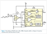
Find attachment for circuit diagram which i used n simulation results
22.JPG11.JPG135-10381.png
 

The circuit has an unipolar input and shouldn't be used with a bipolar AC input voltage. Start your tests with a variable positive DC voltage.
 

I have tried dc-power, n as u said i again tried but results are same..
 

Why does the opamp have positive feedback and negative feedback at the same time?

- - - Updated - - -

Your circuit looked strange so I looked in Google and found many circuits similar to this one:
 

Attachments

  • voltage to frequency converter.png
    voltage to frequency converter.png
    25.1 KB · Views: 226

I tried this circuit .. its also not working ... :bang:

3.JPG33.JPG
 

Why does the opamp have positive feedback and negative feedback at the same time?
It's a well-known current source circuit. The capacitor is charged with a current proportional to input voltage.

I tried this circuit .. its also not working
The circuit looks wrong. Don't see how it should work with positive input voltage.
 

Hi,

at first the pot is connected wrongly. This way you can not adjust.

**
The first OPAMP is an integrator. It regulates in a way, that IN- input has the same voltage than IN+ input.
--> therfore (as long as it is inregulation) IN- = 0V
--> therfore the discharge of the NE555 has no function.

With positive voltage of V3 (as FvM said) the output of the OPAMP will go to it´s negative limit.

Klaus
 

therfore the discharge of the NE555 has no function.
Besides need to flip the input voltage, I wondered how the capacitor can be discharged.
I guess it can work with a bipolar LM555 (but not the 555 CMOS version) by utilizing the small positive output voltage of the saturated switch transistor, about 5 mV with 15V supply
 

Ohk Guys, thank you for suggestions,, sorry for positive input, but its still not as expected .. but what you can say now results can be achieve by some change in resistance n capacitance ?? or its cant still work ??..

New Results are find in attachment ...
thank you guys ..
4.JPG5.JPG6.JPG
 

its still not as expected
What do you mean? I see that the simulation has stopped in the middle. But the waveforms look regular up to this point.
 

Hi,

I wondered how the capacitor can be discharged.
I guess it can work with a bipolar LM555 (but not the 555 CMOS version) by utilizing the small positive output voltage of the saturated switch transistor, about 5 mV with 15V supply

I don´t think it works, because connecting a "virtual GND" to a true "GND" will not cause any useful current to flow. And if, then it won´t directely discharge the capacitor, because the other connection of the capacitor has the high voltage referenced to GND.

--> My solution is a CMOS switch (with current limiting resistor. 100R?) across the C.

Klaus
 

The datasheet for the LM324 and LM358 opamps has a simple VCO circuit.
 

Attachments

  • LM324 VCO.PNG
    LM324 VCO.PNG
    29.2 KB · Views: 119

Hi,

this really seems to be a smart solution.

Maybe the use of optimized OPAMPs and a FET instead of the bjt could bring (small) improvements.


Klaus
 

i have another circuit diagram .. guys what u can say about this ??
guys .. i know it is possible to implement through 741 n 555 .. bt how i have to find .. help me to short it out

circuit diagram.JPG
 

The circuit itself is very, very simple, and all the components are inexpensive and readily available.

Why don't you breadboard it instead?
Simulations may have all sorts of initialization and convergence issues.
 

Status
Not open for further replies.

Part and Inventory Search

Welcome to EDABoard.com

Sponsor

Back
Top