Buriedcode
Full Member level 6
Hi,
I'm current introducing myself to microwave design with a project - designing a test board for a 2.4Ghz transceiver using the ML2724. Thanks to the manufacturer, I have a few evaluation board schematics to look at, analyze/copy. These are great not just for copying subcircuits, but also for educational purposes, so I can see what each components does and why its value was chosen.
Although I have read up on baluns, one part bugs me. That is, differential matching. The balun they use is a 50/50 ohm hybrid ceramic balun (LDB212G4005C-001), so thats a balanced port impedance of 50 ohms. The TX output of the transceiver has two pins, one is a compliment of the other, both 12+j0 impedance.
Now, although I have a schematic for a matching network, I'm using smith charts to verify it, so I have a better understanding of whats going on. We have a differential output from the TX, two pins at 12+j0 - so thats a differential impedance of 24+j0 right? Now, the balun has a differential/balanced input impedance of 50 ohms. Does this mean that one could 'split' the matching network into two single ended matches? So instead of thinking 24+j0 -> 50+j0, I could think of it as 12+j0 -> 25+j0?
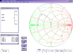
I have used a smith chart, and with a 'load' of 50ohms (input to balun) and using the components and values in the reference schematic, it brings me to 11.8+j0. - pretty damn close. However, the series capacitor must be double its value in order to get to 11.8+j0.
So..... I am confused, since I would have thought the above would be the case if the load impedance was 25 (half of our 50 ohm balanced input)... or is the differential impedance of the balun actually 100 ohms?
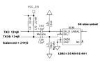
A picture is worth a thousand words, so I've included two. First is a snippet of the reference schematic. Two 12+j0 pins to a 50ohm balun, using 1.8nH and 1.5pF caps. The second was my own test on a smith chart, to convert just one pin, at 12+j0 (singled ended) to 50ohm. The inductance is the same, but why is the series capacitor double the value of the differential match? (3.0pf, instead of 1.5p). I read somewhere that this value, should in fact, be half of the differential match (0.75pf on the single ended). I'm guessing I'm not fully understanding it.
Any answers are welcome, thanks!
Buriedcode
I'm current introducing myself to microwave design with a project - designing a test board for a 2.4Ghz transceiver using the ML2724. Thanks to the manufacturer, I have a few evaluation board schematics to look at, analyze/copy. These are great not just for copying subcircuits, but also for educational purposes, so I can see what each components does and why its value was chosen.
Although I have read up on baluns, one part bugs me. That is, differential matching. The balun they use is a 50/50 ohm hybrid ceramic balun (LDB212G4005C-001), so thats a balanced port impedance of 50 ohms. The TX output of the transceiver has two pins, one is a compliment of the other, both 12+j0 impedance.
Now, although I have a schematic for a matching network, I'm using smith charts to verify it, so I have a better understanding of whats going on. We have a differential output from the TX, two pins at 12+j0 - so thats a differential impedance of 24+j0 right? Now, the balun has a differential/balanced input impedance of 50 ohms. Does this mean that one could 'split' the matching network into two single ended matches? So instead of thinking 24+j0 -> 50+j0, I could think of it as 12+j0 -> 25+j0?
I have used a smith chart, and with a 'load' of 50ohms (input to balun) and using the components and values in the reference schematic, it brings me to 11.8+j0. - pretty damn close. However, the series capacitor must be double its value in order to get to 11.8+j0.
So..... I am confused, since I would have thought the above would be the case if the load impedance was 25 (half of our 50 ohm balanced input)... or is the differential impedance of the balun actually 100 ohms?
A picture is worth a thousand words, so I've included two. First is a snippet of the reference schematic. Two 12+j0 pins to a 50ohm balun, using 1.8nH and 1.5pF caps. The second was my own test on a smith chart, to convert just one pin, at 12+j0 (singled ended) to 50ohm. The inductance is the same, but why is the series capacitor double the value of the differential match? (3.0pf, instead of 1.5p). I read somewhere that this value, should in fact, be half of the differential match (0.75pf on the single ended). I'm guessing I'm not fully understanding it.
Any answers are welcome, thanks!
Buriedcode
") And it has several low pass, and band pass 2.45Ghz ceramic filters after the TX chain, I guess that is how they suppressed the higher frequencies there. But I will look into a LP match, as it might prove better to lower band interference with my other transceivers I'm testing.
And it has several low pass, and band pass 2.45Ghz ceramic filters after the TX chain, I guess that is how they suppressed the higher frequencies there. But I will look into a LP match, as it might prove better to lower band interference with my other transceivers I'm testing.
