pawan kumar
Member level 4
Hello Friends,
I know, it's late to ask this question which should have been silly 6 years ago.
Please help me understand this at least now.

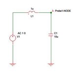
The image above is that of an LC low pass filter. On running an AC frequency response analysis, there is an increase in Voltage before it starts rolling off.

I analyze the circuit by calculating it's transfer function which is
Vout/Vin = 1 /(1+W^2LC)
here I intend to mean omega as 'W'.
I am not able to understand how there can be an increase in voltage when there is no Amplifier attached to it.
Thanks in advance for your help.
I know, it's late to ask this question which should have been silly 6 years ago.
Please help me understand this at least now.

The image above is that of an LC low pass filter. On running an AC frequency response analysis, there is an increase in Voltage before it starts rolling off.

I analyze the circuit by calculating it's transfer function which is
Vout/Vin = 1 /(1+W^2LC)
here I intend to mean omega as 'W'.
I am not able to understand how there can be an increase in voltage when there is no Amplifier attached to it.
Thanks in advance for your help.