Continue to Site

Welcome to EDAboard.com

Welcome to our site! EDAboard.com is an international Electronics Discussion Forum focused on EDA software, circuits, schematics, books, theory, papers, asic, pld, 8051, DSP, Network, RF, Analog Design, PCB, Service Manuals... and a whole lot more! To participate you need to register. Registration is free. Click here to register now.

Bandpass filter why we are cascading HPF+LPF why not LPF +HPF,both are LTI systems

Status
Not open for further replies.

hioyo

Advanced Member level 4
Joined
Aug 18, 2021
Messages
116
Helped
0
Reputation
0
Reaction score
2
Trophy points
18
Activity points
899
Dear Team,

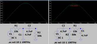
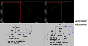
For the bandpass filter why we are cascading HPF and LPF why not LPF and HPF.

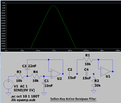
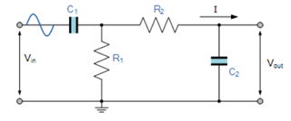
Below is the circuit of a BPF.

My question is for an LTI system if we put LPF 1st and HPF 2nd of HPF 1st and LPF 2nd, we need to get the same response.

But in all places I searched I found 1st stage is HPF and 2nd stage is an LPF.

May I know why it is like that?


Regards

HARI
 

The second very simple passive filter affects the first on
You mean HPF+LPF combination will have better frequency response.Please correct me if I am wrong.
May I know about the noise performance of the combinations HPF+LPF and LPF+HPF
 

You mean HPF+LPF combination will have better frequency response
Both have different frequency response. What is better depends on your specification.
To reduce the load effect, you can simply increase the impedance of the second RC circuit by a factor, the difference between both frequency responses almost disappears.

1652867452026.png
 

Attachments

  • poor mans bandpass.zip
    930 bytes · Views: 111

The passive filters have very gradual cutoffs at each side of the peak frequency. If that is not good enough then you should use active filters with an opamp like this:
 

Attachments

  • active bandpass.png
    active bandpass.png
    29 KB · Views: 115
Hi,

My interpretation of bandpass as high pass followed by low pass:

High pass = NOT under x (lower) frequency
+
Low pass = NOT over y (higher) frequency

Bandpass = only pass signals that are NOT under x lower frequency & NOT over y higher frequency

I guess if they were configured the other way round (LPF + HPF), the LPF would also cut off the frequency range of the signal of interest.
 

I guess if they were configured the other way round (LPF + HPF), the LPF would also cut off the frequency range of the signal of interest.
No. As stated correctly in post #1, ideal LPF and HPF can be cascaded in any order without changing the total frequency response. Problem is that the ideal frequency response is only achieved with zero source and infinite load impedance of each first order filter. Inserting a buffer between both filters fixes the problem, also scaling the impedance of the second filter as shown in post #4.
 
  • Like
Reactions: d123

    d123

    Points: 2
    Helpful Answer Positive Rating
My simulation reveals little or no difference in response between the two configurations.

However the CRRC arrangement is easier to customize.
Example, greater voltage and Amperes are conveyed by using larger input C and lesser output C.

compare bandpass CRRC vs RCCR 31kHz center freq (disparate C val).png
 

Status
Not open for further replies.

Part and Inventory Search

Welcome to EDABoard.com

Sponsor

Back
Top