hddn
Newbie
Hello everyone,
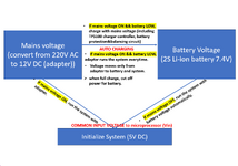
I have a PCB design that is powered by mains electricity via an adapter. When mains electricity ON, I want it to switch to li-ion battery mode and provide energy. When mains electricity OFF, the battery must not provide energy. At the same time, I want the battery to be charged from the circuit when not in use.
The battery will be embedded, it cannot be taken out and charged. How to split battery voltage and adaptor voltage? Which components should I use?
I can say that it works like computers battery system.
That is, if the system is working with the adapter, there must be no voltage coming from the battery to the system.
If there is no mains electiricty, the battery must be activated and the system must be operated. There should be no energy flowing to the adapter.
The battery should only be activated automatically when there is no mains electricity. I've attached a flowchart.
I didn't know how to do this.
If you have any information, I would like your help.
Thanks in advance.