Continue to Site

Welcome to EDAboard.com

Welcome to our site! EDAboard.com is an international Electronics Discussion Forum focused on EDA software, circuits, schematics, books, theory, papers, asic, pld, 8051, DSP, Network, RF, Analog Design, PCB, Service Manuals... and a whole lot more! To participate you need to register. Registration is free. Click here to register now.

Bandgap voltage variation in different corner

Status
Not open for further replies.

gn7623233

Newbie level 6
Joined
Oct 18, 2016
Messages
12
Helped
1
Reputation
2
Reaction score
0
Trophy points
1
Activity points
148
Hi,

I have designed a bandgap, it works fine.
And different corners have different curvature.
One thing i wanna know is :
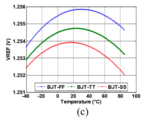
Why FF (SS) corner has larger (lower) voltage than TT corner at the same temperature.
Just like the figure 5.(C) https://reurl.cc/j741dn
Is it about the doping concentration influence the saturation current (Is) or other factor?
THANKS!
 

Hi,

Link doesn't work for me. It opens an empty, white page...
 

Resistance (resistivity) may be moved by the corners.
You'd have to look at the models chain.

Tempco tends to be proportional to resistivity. This I
think is also true of its curvature. Although a "digital"
process's modeling of "analog" features must always
be viewed with suspicion. A NWell resistor is a bad
choice for tempco curvature reason, as well as voltco.
Bandgap designers may like the high resistor TC for
compactness, initially - until its curvature bites them.

Thin film resistors (not poly) have near-zero tempco
and curvature. In modern mixed signal technologies
these tend to reside in the lower levels of the
interconnect stack, not on field oxide. However using
these may make your bandgap block incompatible
with the "low rent" flow variants, it's a process steps
adder that may be cut for cost.
 

Attachments

  • 擷取.PNG
    擷取.PNG
    13 KB · Views: 218

    d123

    Points: 2
    Helpful Answer Positive Rating
I would look into the schematic and see voltages and currents to compare FF vs TT to find the reason. The bias current that biases badgap (opamp that is used in the bandgap) varies with corners and it affects the final bandgap voltage.
 

Status
Not open for further replies.

Part and Inventory Search

Welcome to EDABoard.com

Sponsor

Back
Top