Vermes
Advanced Member level 4
A system STMPE811 from ST Micro was used in this project. Quality, speed, accuracy and interesting possibilities offered by the chips, with their small size and convenient use with the I2C are strongly in favour of their use.
This is how it looks on the PCB:

Now some information about basic start of the touch panel of such a chip. It is difficult to find a description of its use with AVR, on the other hand it is even smaller than the AR1020 when it comes to pins and the application is not complicated. Only the housing QFN16 may be problematic to solder if someone does not practice.
Schema:
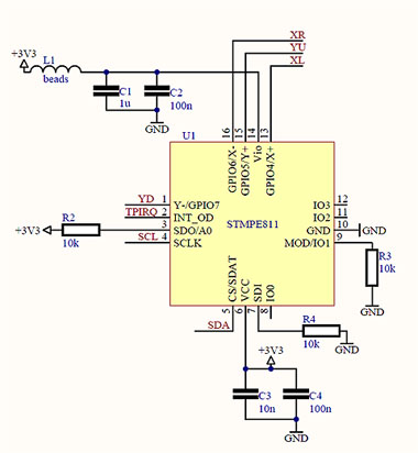
The system has the following possibilities: detecting the coordinates of the touch, but also the fact of touch and release. The system is powered by voltage 3,3V and the same voltage powers the microcontroller, moreover, also LCD works on 3,3V. Thanks to that, there is no need to use any conversion.
Speed and accuracy is excellent. System has 12-bit ADC converters, but the resolution was reduced to the 9-bits, and in this case it is sufficient. The system requires initialization and setting a lot of registers to start normal operation. Below, the initialization specially prepared for this purpose:
Code:
Kod C - [rozwiń]
void stmpe811_init() {
        stmpe811_write_reg( 0x04, 0x0c );
        stmpe811_write_reg( 0x0a, 0x07 );
        stmpe811_write_reg( 0x20, 0x49 );
        _delay_ms(2);
        stmpe811_write_reg( 0x21, 0x01 );
        stmpe811_write_reg( 0x17, 0x00 );
        stmpe811_write_reg( 0x41, 0x9a );
        stmpe811_write_reg( 0x4a, 0x01 );
        stmpe811_write_reg( 0x4b, 0x01 );
        stmpe811_write_reg( 0x4b, 0x00 );
        stmpe811_write_reg( 0x56, 0x07 );
        stmpe811_write_reg( 0x58, 0x01 );
        stmpe811_write_reg( 0x40, 0x03 );
        stmpe811_write_reg( 0x0b, 0xff );
        stmpe811_write_reg( 0x09, 0x03 );
}
The support of interruption on INT0 is different than the one presented in the attachment on the original thread.
Code:
ISR( INT0_vect ) {
        stmpe811_read_buf( 0x0b, 1, buf);
*
        if( buf[0] & 0x02 )  {
                stmpe811_read_buf( 0x4d, 2, buf);
                stmpe811_read_buf( 0x4f, 2, &buf[2]);
*
                stmpe811_write_reg( 0x0b, 0x02 );
                int0_flag = 1;
        } else {
                stmpe811_write_reg( 0x0b, 0x01 );
        }
}
Otherwise than in the code of the PDF in the attachment, 16-bit registers containing coordinates X and Y are read at once. Z was skipped. The values in these registers are 12-bit. In the interruption, the records read are loaded into the buffer, to the next cells and the flag is set, which is checked later in the main loop. In the main loop you can reduce the bit resolution, and also convert the ADC values to a specific coordinates X and Y. Depending on them, and whether the screen is touched or not – there is a circle around the touch. There are also at this time coordinates X and Y. With the coordinates, you can analyse where you touch with your finger or stylus and depending on it – to implement various functions.
Link to original thread (useful attachment) – AVR - Panel dotykowy - stmpe811 - I2C