Vermes
Advanced Member level 4

It is a construction of the fish feeder for aquarium enthusiasts who do not know very much about the electronics.
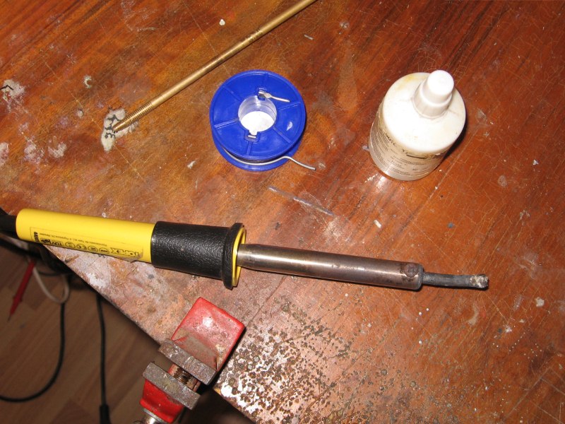
First thing is construction of the screw. Brass or copper rod (fi 3-5mm) and galvanized, copper or brass washers with an internal diameter corresponding to the diameter of the rod and outer diameter corresponding to the diameter of the tube, in which the screw will work. To solder it, use independently heated or gas soldering iron, because others do not provide the right temperature. In order to solder the galvanized washers, the temperature needs to be high. A soldering flux for zinc will be helpful, but rosin should be also enough. Cross the washers as in the photo, making sure that all the washers bend in the same direction. Then the washers should be soldered to the rod, trying to get the regular shape of the screw. The screw length should be chosen according to the size of the feeder.

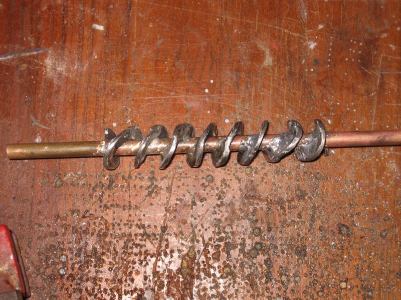
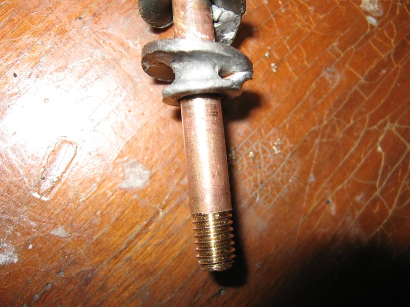
Soldered screw has to be checked by inserting it to the tube where it will be working. If the screw is too large, it can be easily sanded down in the table grinder. It should turn loose in the tube. At one of the end washers, a smaller washer has to be soldered. Its role is to ensure adequate distance from the feeder's wall.
Further step is to cut the tube. The top of a width corresponding to the size of the feeder should be cut off. Then cut out the outlet and adjust the trigger of the tube.
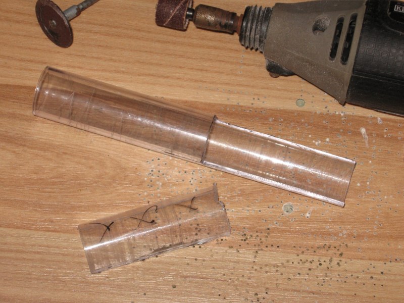
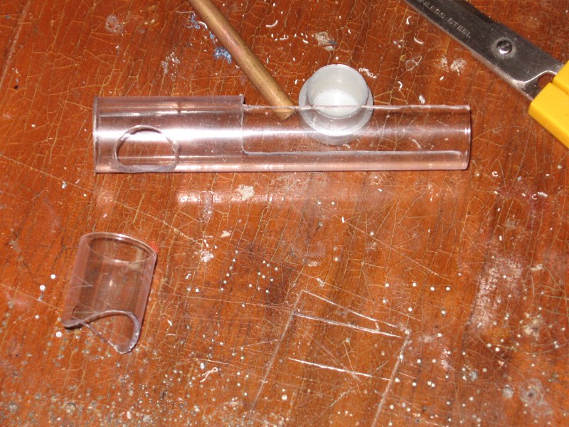
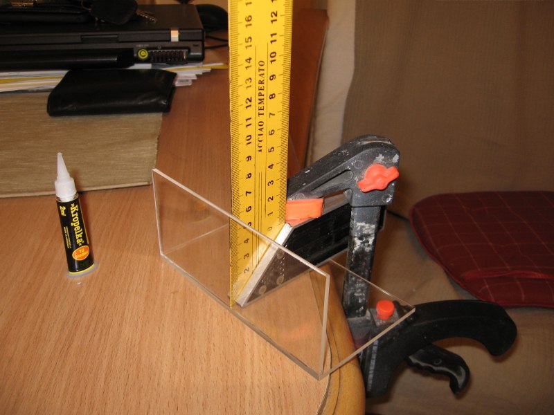
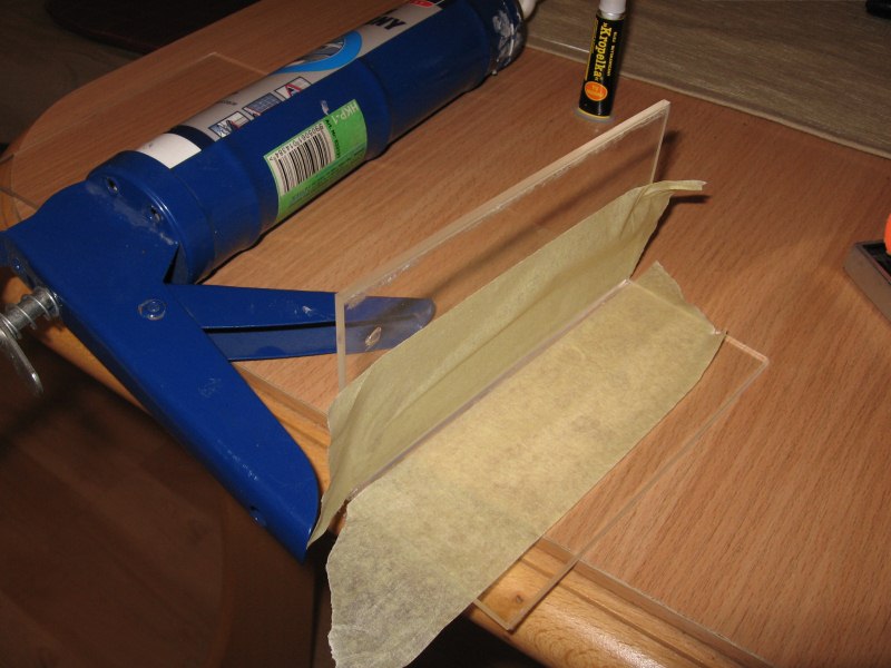
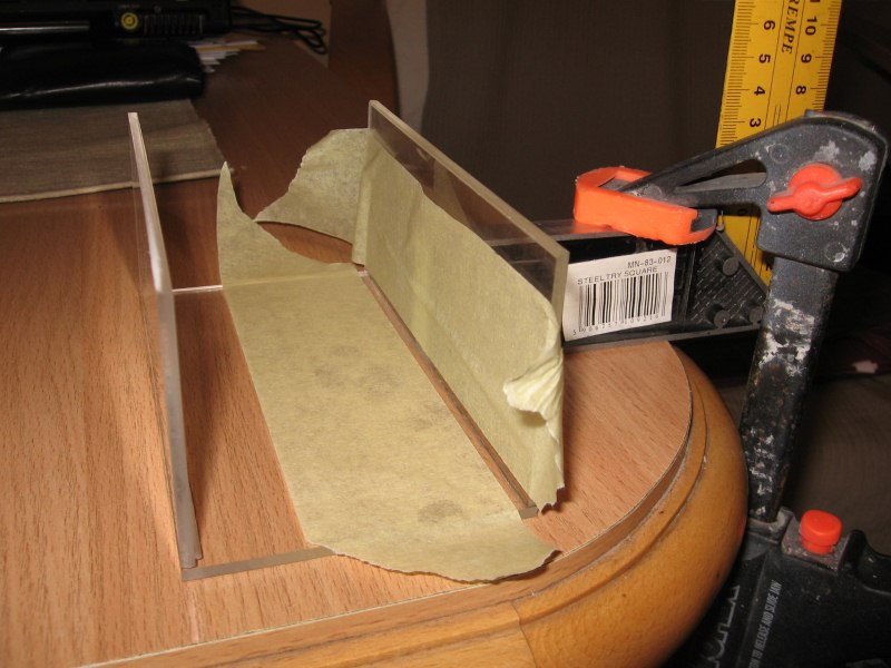
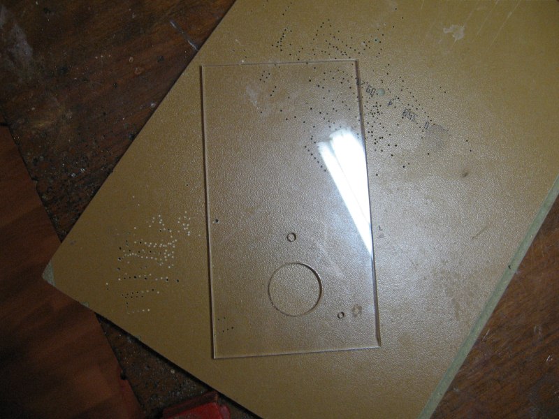
Next, cut the walls of plexiglass. For this purpose use a special knife for plexiglass, with which you only have to outline the plate a few times and break it on the edge of the table. Additionally, the edges were sealed with silicone. It prevents possible spillage of fine food through the leaks on the walls connections. Then paste the tube, in which the screw will work. While determining its position relative to the edge, account of the size of the engine and gear. When determining the size of the feeder, it should be taken into account whether the driver will be placed in the feeder or separately, such as in this project.


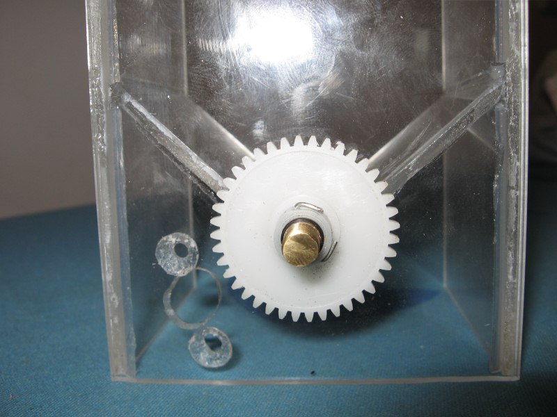
Place the screw in the tube. Gap between the axle and gear wheel hole can be deleted using the shrink t-shirts. The gear wheel was blocked drilling the axis and thread a piece of wire. Having already installed the wheel, we can measure the holes for mounting the engine.
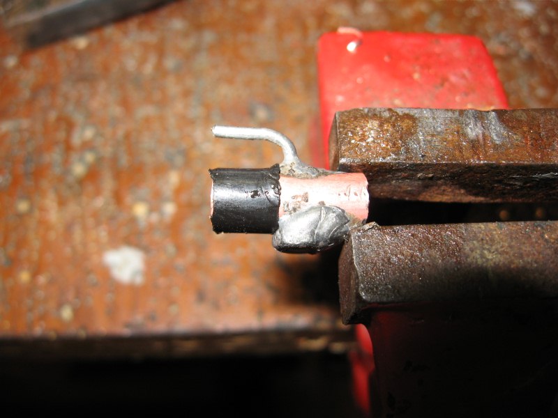
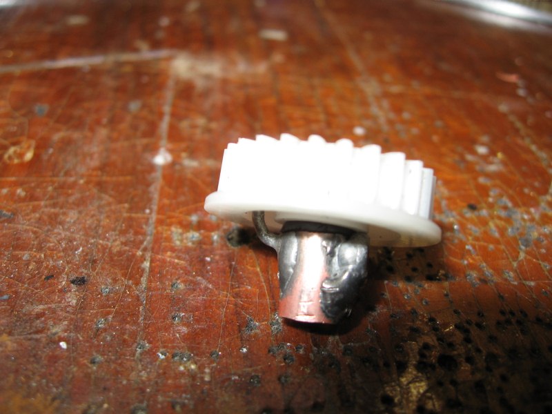
To mount the gear wheel on the engine, a piece of copper pipe was used. A wire that blocks the wheel so it does not rotate relative to the shafts, was soldered to the copper pipe. Elsewhere, the tube is drilled and the nut 2,5mm is soldered. A screw clamping the axle to the motor is screwed into the nut.
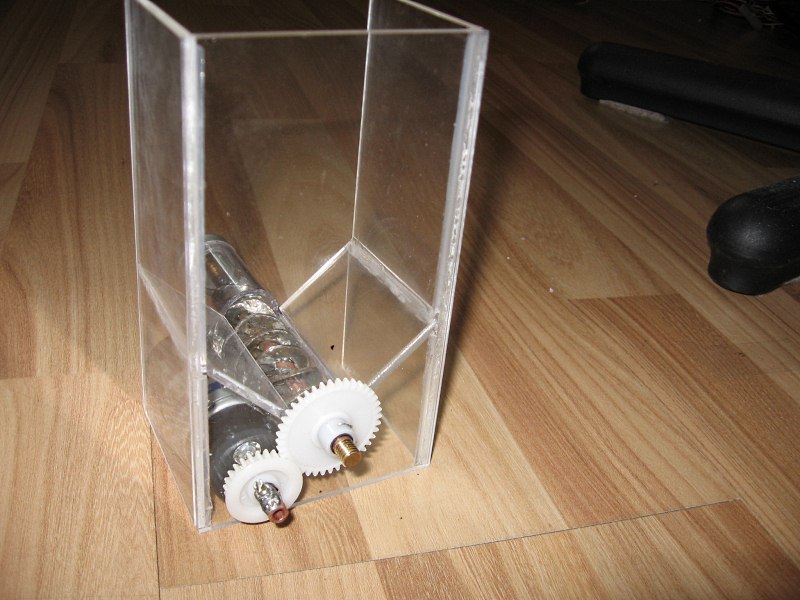
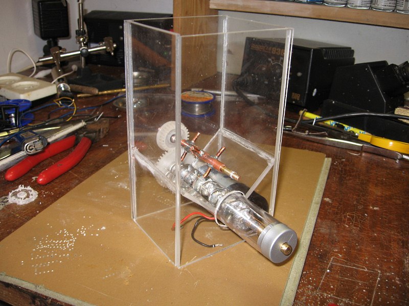
Everything compound together.
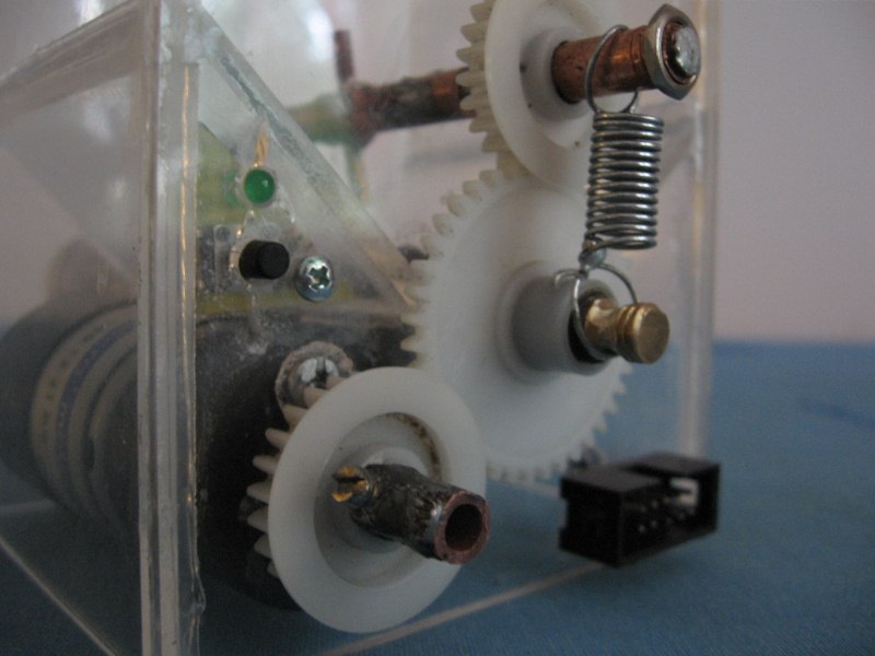
Now the feed stirrer, whose role is to prevent the feed hanging. It is an essential element. Axle was made of 3mm fi rod, a 5mm fi tube was soldered to its end. The tube deleted the difference between the diameter of the axle and the hole in the gear wheel. One side of the axle was threaded. Pieces of wire were soldered to the second copper tube. All was pulled on the gear wheel, drilling holes for the locking wire.

Then cut the needed holes in the front panel and fold the mixing wheel. Check if everything fits.
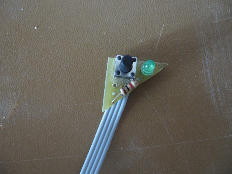
Now, mount the switch that allows for manual triggering the dose of food. This is a very useful feature, because without reprogramming the timer, you can specify the dose of food. In addition, a power control of the feeder can be made. All that was soldered on an universal board and pasted to the feeder. The resistor visible on the board is designed to allow connection of the diode 3V to the power supply 12V. The resistor should be chosen from the range of 220ohm to 1kohm. 10-pin socket which uses three pairs of contacts – the engine power, diode control and manual switch was used as a connection with the driver.
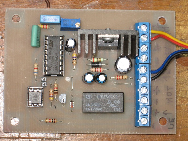
The driver allows to run the feeder with fixed speed of the screw for a set time (from one to several seconds). The feeder is triggered by a pulse from 5-12V power supply, actuated by e.g. a simple timer.
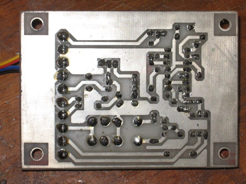
The board of the driver:
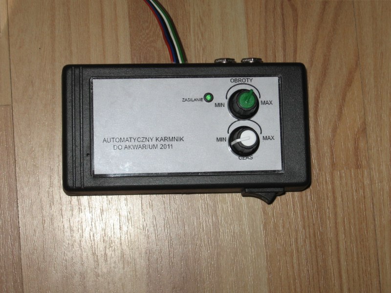
The housing of the control part:

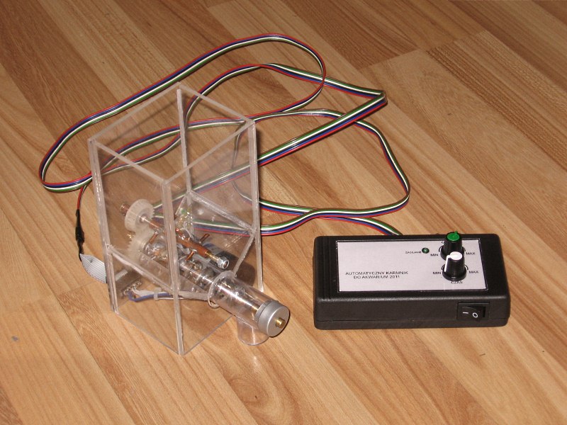
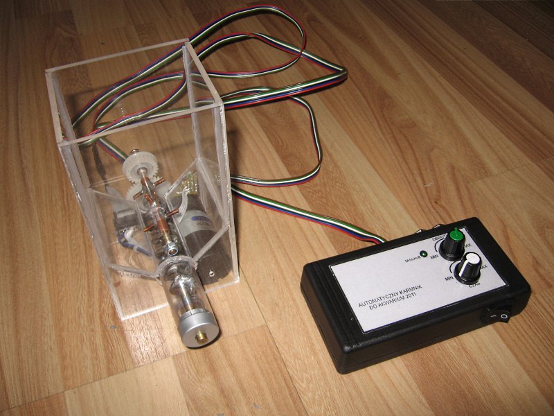
The feeder:
Link to original thread (video + attachment) – Automatyczny karmnik dla ryb v2 - instrukcja budowy