Vermes
Advanced Member level 4

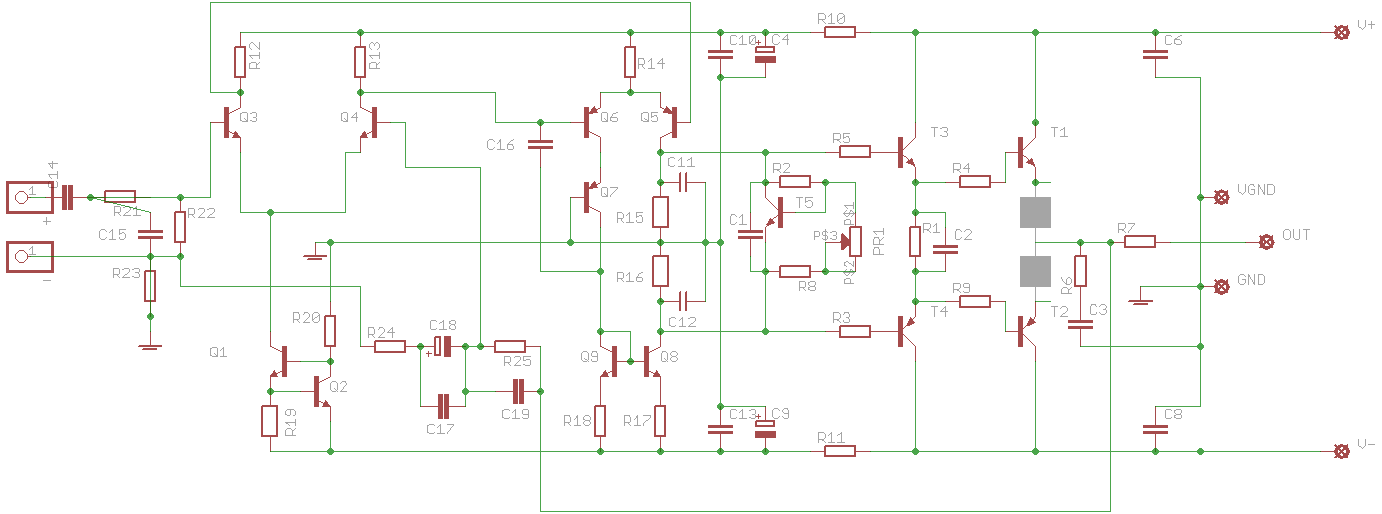
The amplifier presented in this project was designed by M. Bittner – it was described on his web page: LINK.
The only one problem with that device designed by Mr Bittner was that the original PCB operates slightly unstable. What more, it seemed to be too large as for needs of such an amplifier. That PCB was also made without advanced knowledge of creating such things. This decscription presents an alternative version of the PCB.
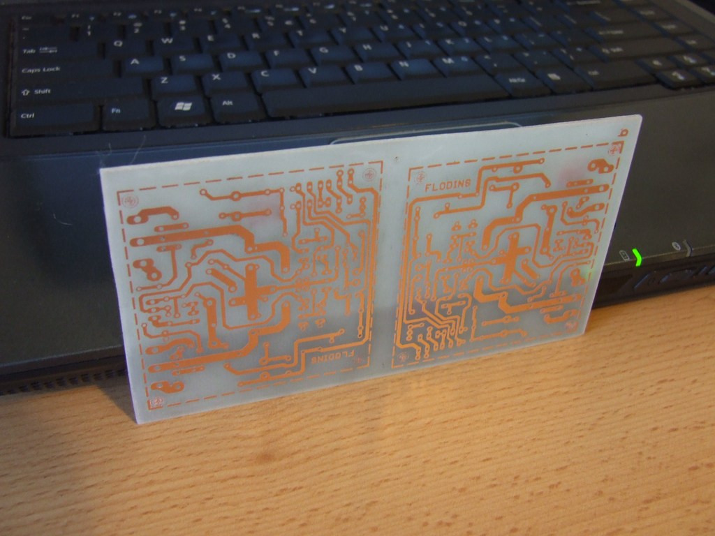
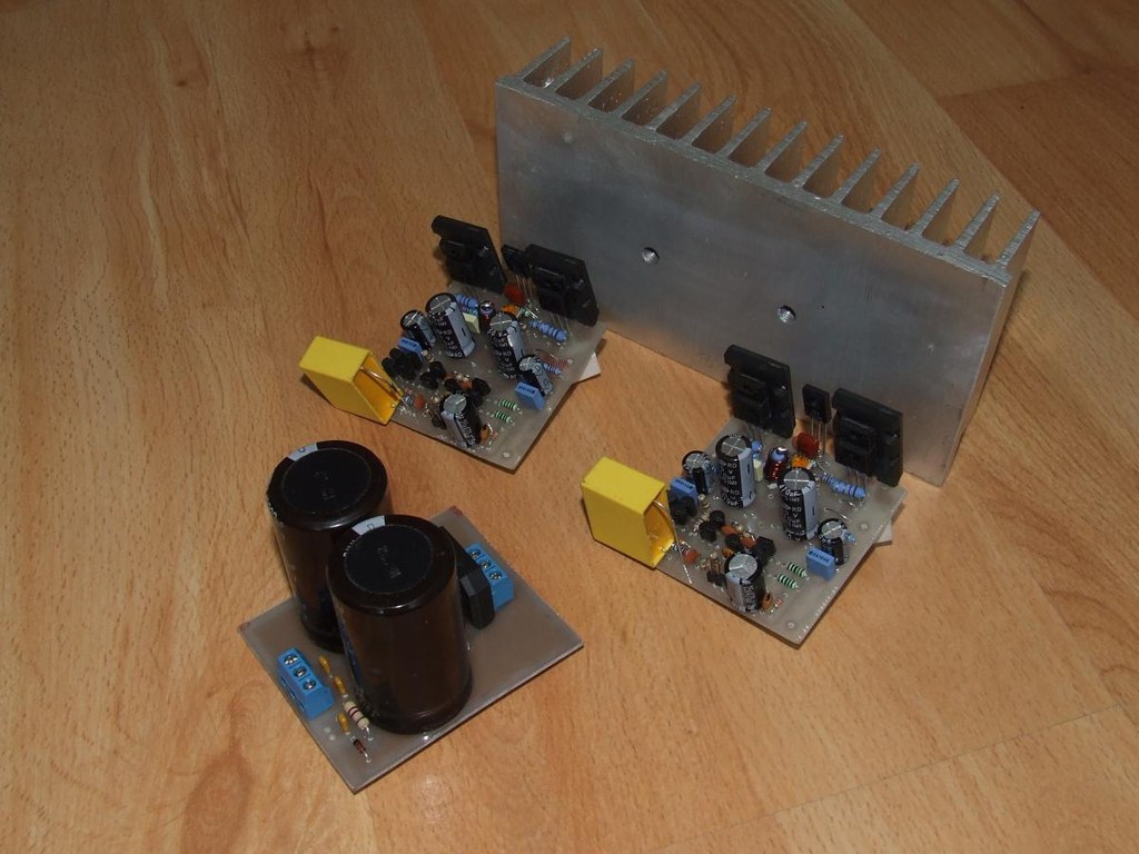
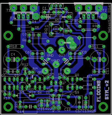
One of the assumptions was to gain symmetry both mechanical and current. The PCB was designed so that there are no problems with conducting caused by too long paths and their wrong location. Dimensions of the prototype: 61x57mm.
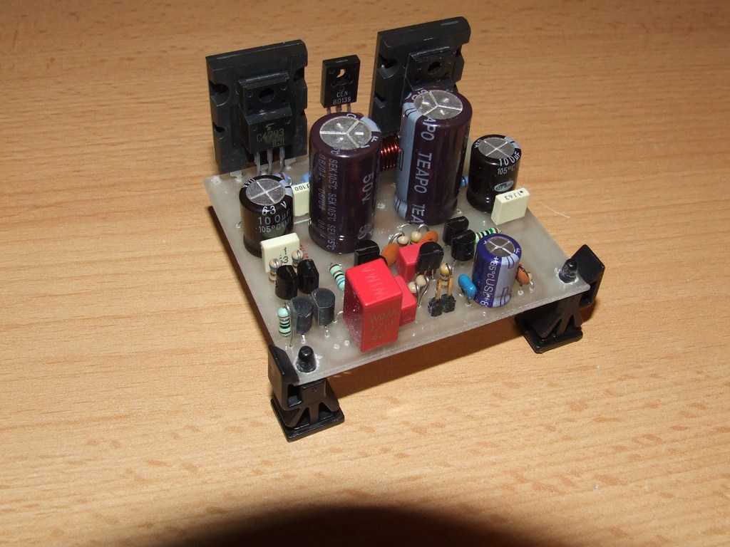
The prototype did well during tests. The PCB was very small and the amplifier operated stable.
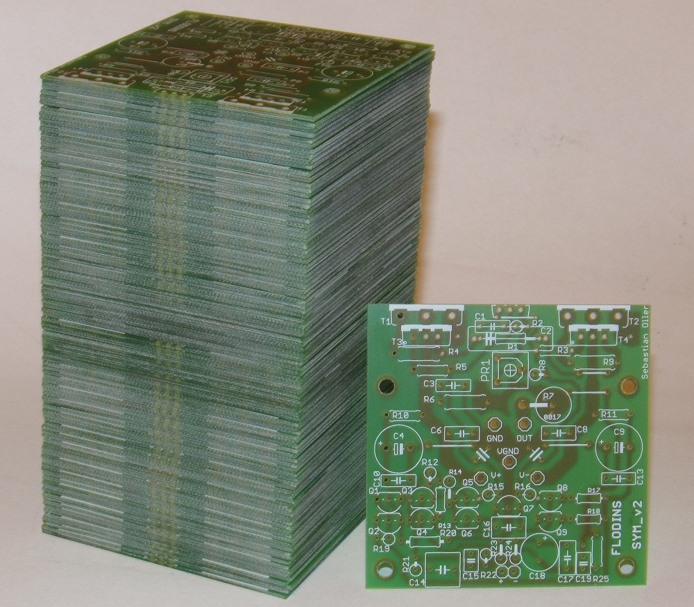
This version had improved symmetry and decreased the length of the feedback path on the side of high impedance. Values of some of the components were improved. Dimensions of the PCB were reduced to 59x58mm.

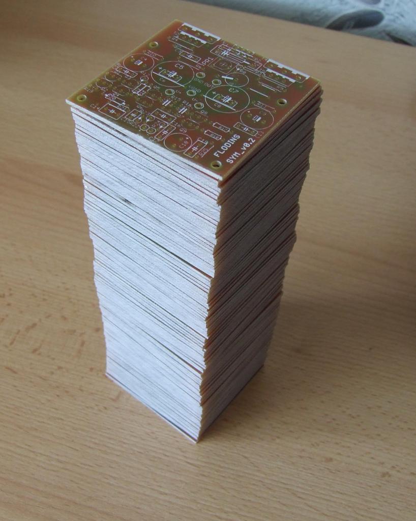
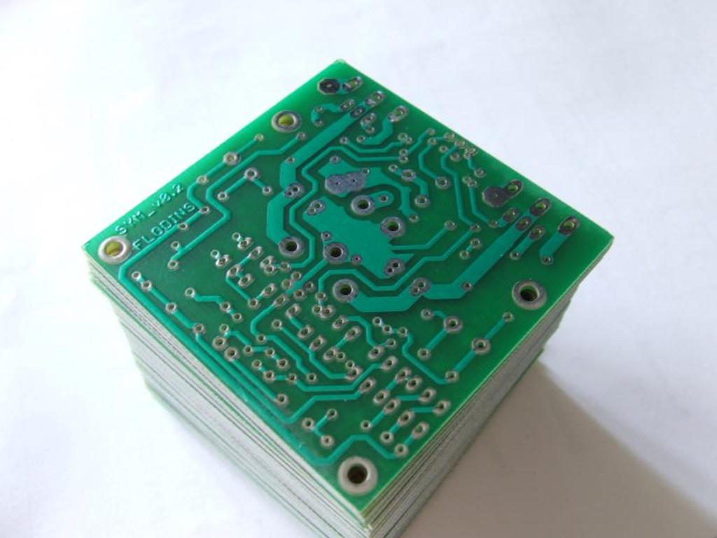
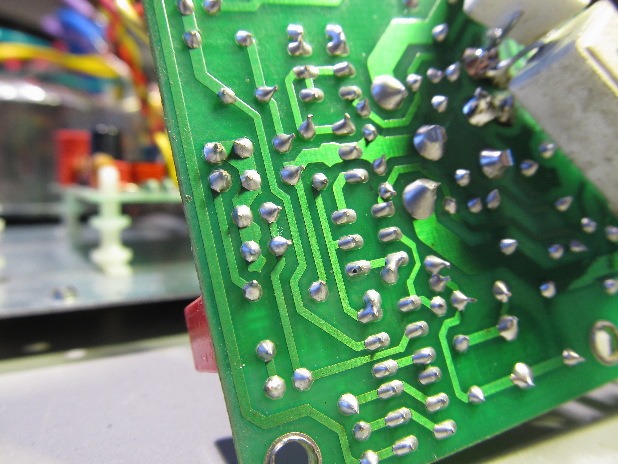
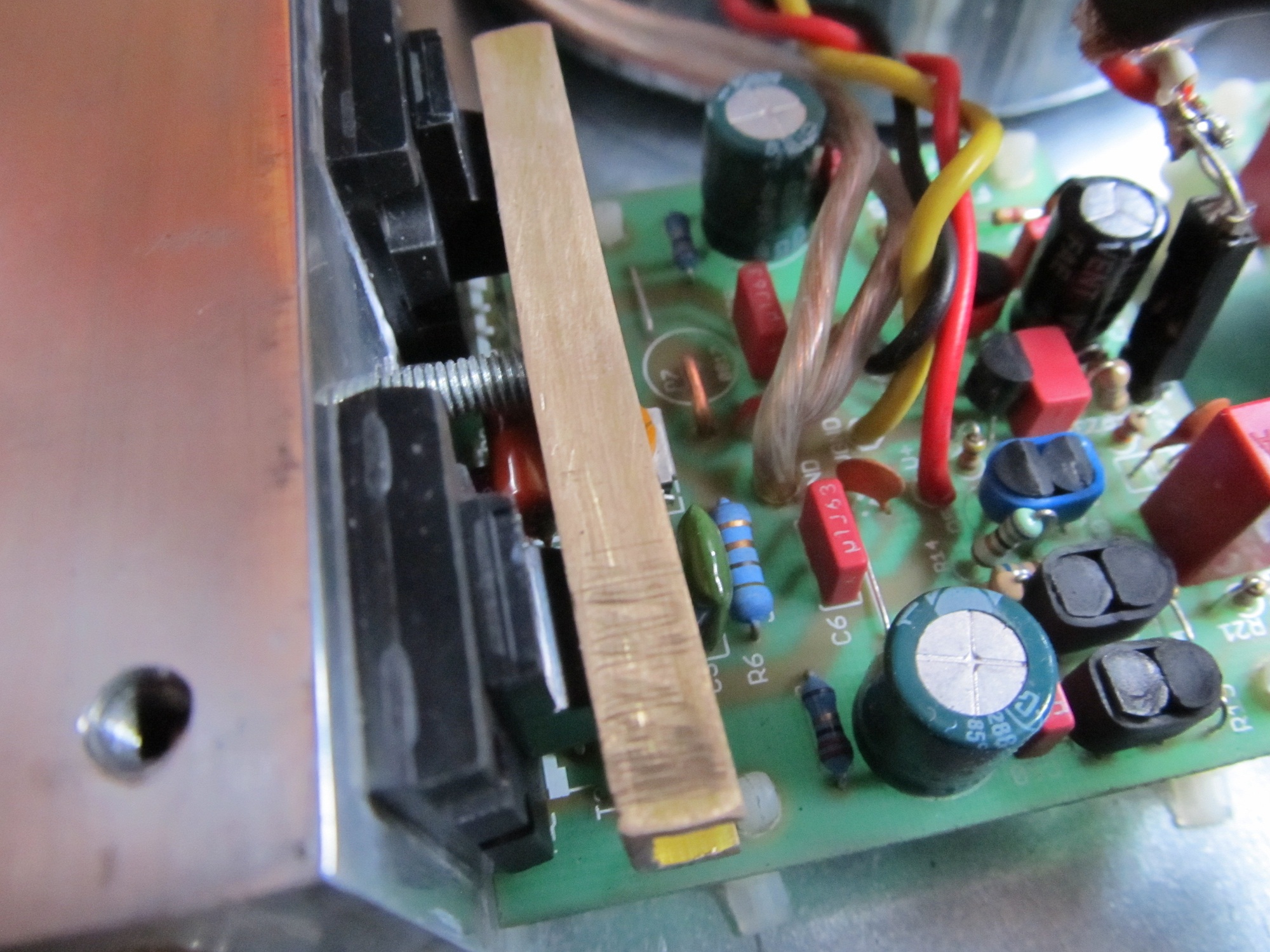
The most important parameter of circuits was the thickess of copper, which was more than 105um.
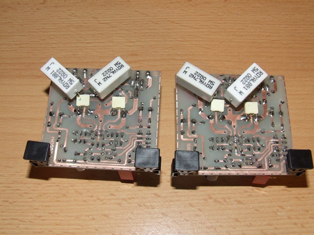
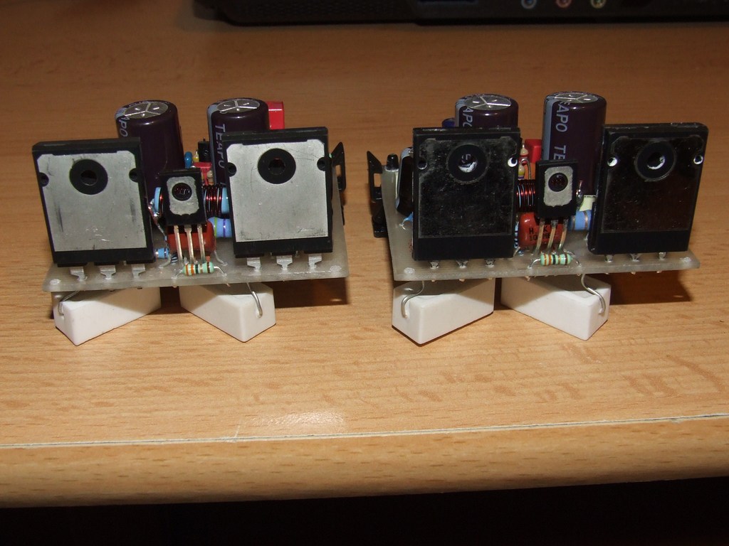
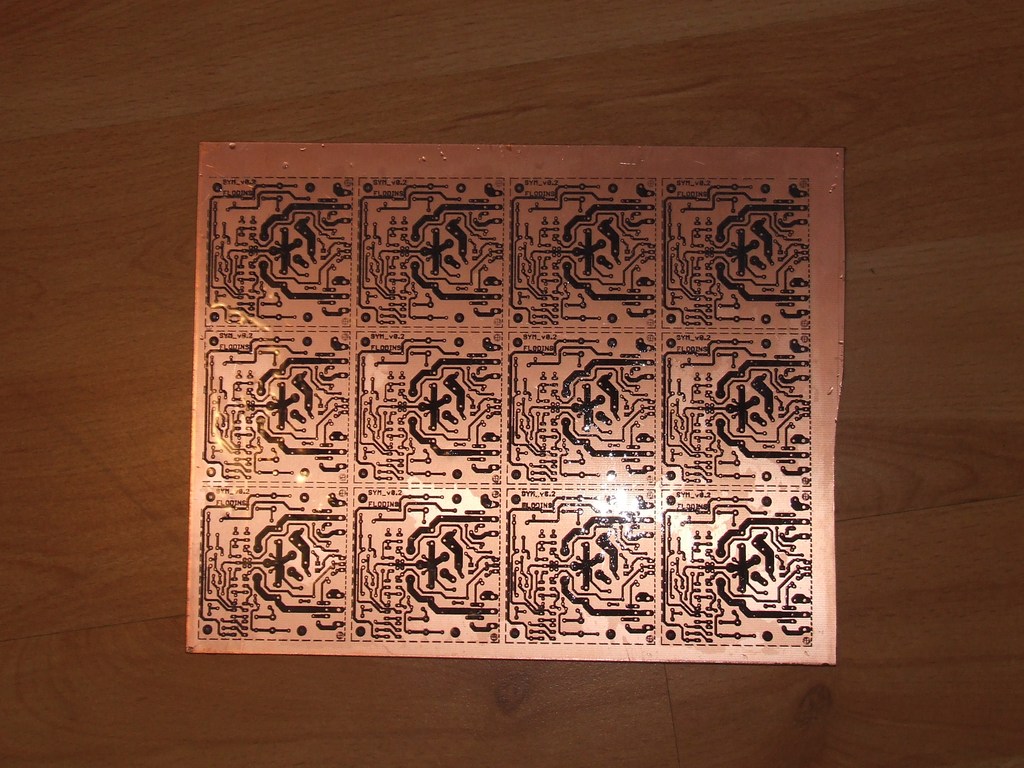
Pictures of two versions of boards (PCBs on the right are the improved version):
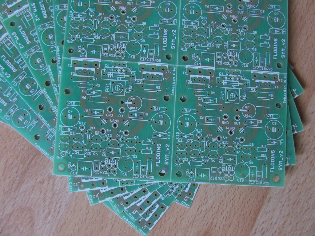
What was done in that version:
- PCBs connected in pairs to be divided (broken)
- 70um copper
- enlarged supply paths, permissible current: 15A per rail
- enlarged mounting holes, for M3 screws
- improved handing and shortening the feedback path from the high impedance
- spacing of transistors was kept, there is no need to change the heat sink
- elimination of electrolytes on the main supply lines
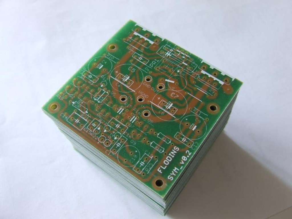
- professional made: indestructible descriptions of white matt, HAL tin, soldermask done properly (before tin), what confirms its resistance
Dimensions: 60x60
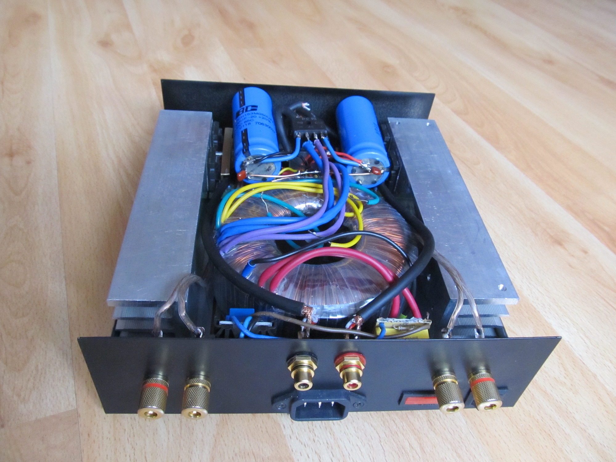
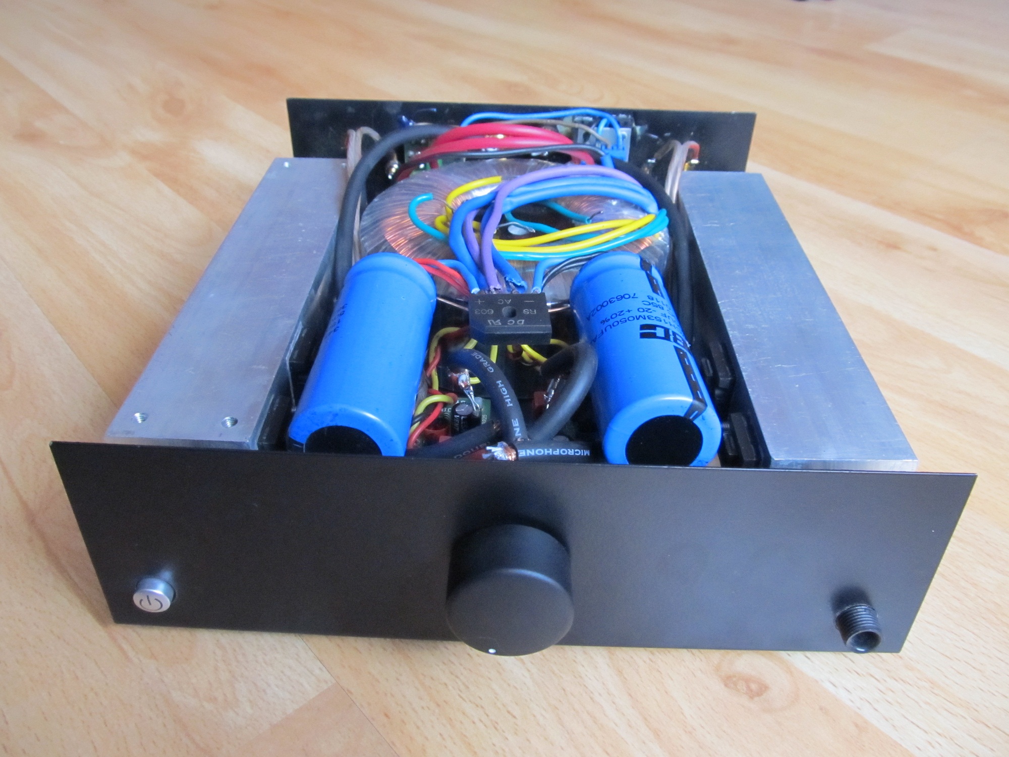
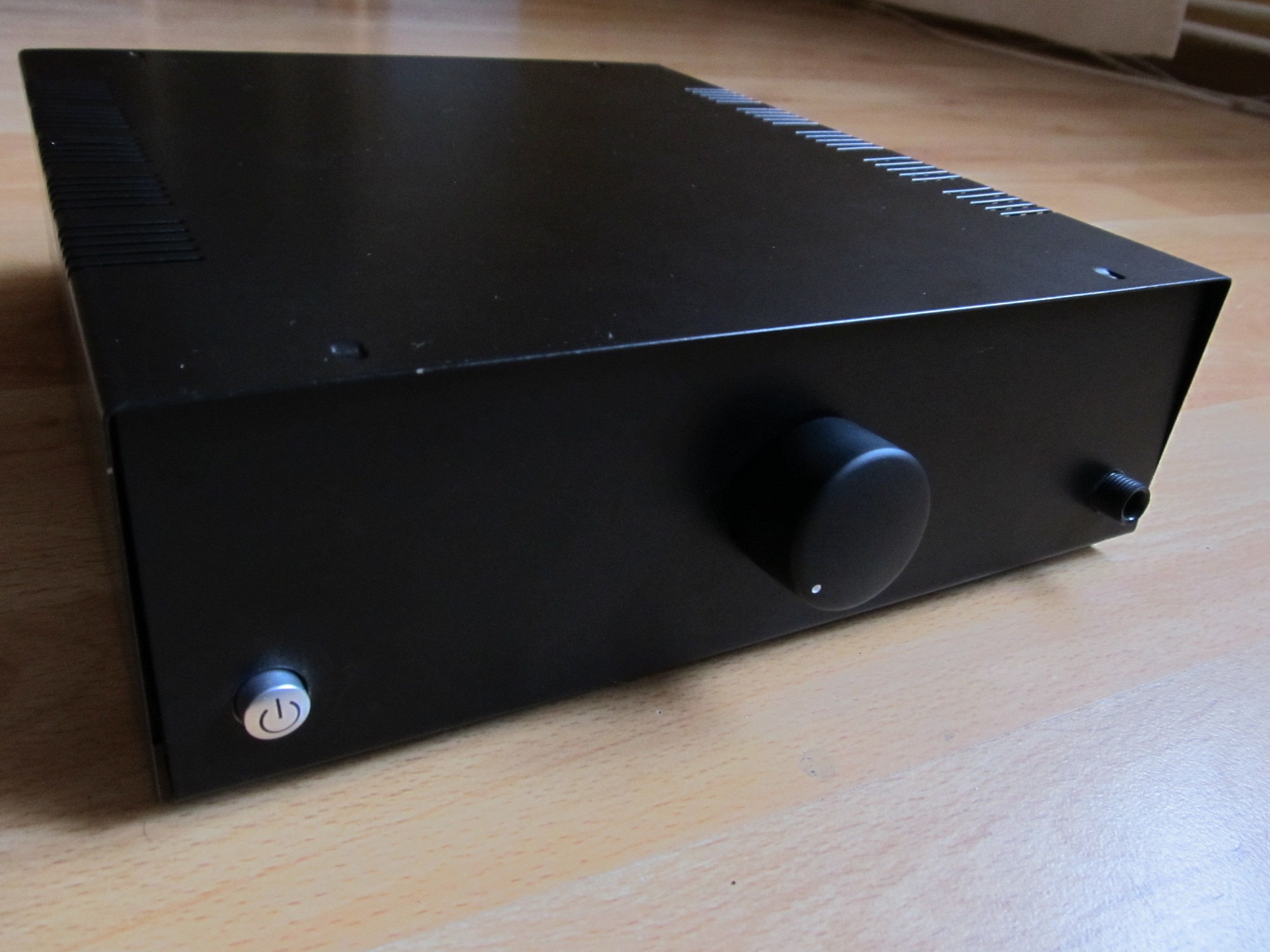
Emi filter and system for turning on the relay using a button on the front panel (for turning on the transformer) can be placed on the housing. Filtering capacitors in the power supply have capacity of 15mF.

Link to original thread (useful attachment) - Wzmacniacz Sym v2 BlackBox