Continue to Site

Welcome to EDAboard.com

Welcome to our site! EDAboard.com is an international Electronics Discussion Forum focused on EDA software, circuits, schematics, books, theory, papers, asic, pld, 8051, DSP, Network, RF, Analog Design, PCB, Service Manuals... and a whole lot more! To participate you need to register. Registration is free. Click here to register now.

Automatic Emergency Backup Power with Charger

Status
Not open for further replies.
guys,
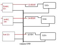
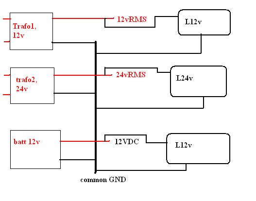
is it possible to use a common gnd for different transformer and battery? positives are different ofcourse... but grounds are tied togather... will it work??
because i'm in this situation... a uC, powered from a trafo will send a high state (5v) to light an led. also it will send this state to a different uC and board... that board and uC is powered from a different source... so if i tie all the GND togather, always current should get a path to come out... and should found a voltage... (if i'm not wrong...)

advice plz...


Mishu~
 

well, guys.. seems it will be finally assembled... i have started to work on pcb.. just 2 more resistors to calculate... then the power board and finally the controller...

well, before that, i am asking one thing for final... about shunt, i found 10W 0.1ohm resistance.. i wanna add them in 4 in parallel for shunt current calculation... and the resistor before the 338, for limiting the current and also for activating the pass transistor, i am using a 1ohm 5W resistor... it will pass only .6-.7 A (600-700mA) that is okey to keep the regulator cool... only heatsink will required at pass transistors... so my question is if i use this 1ohm 5W, then it will develop .65V to .7v for current... and the transistor (4-6in number) will turn on right??

And final question is... I want to sense the 220mains availability (also to read main voltage) for change over... i want a fast changeover.. thus my plan is to detect the un availibility of one cycle of 50hz. means 20ms. so if i use a trafo and then a rectifier and then a filter cap (but very small ofcourse, so clamping of peak will be a very low) then i can get a DC for sensing and adc reading too... but i need to make it for only 20ms period... so fast (less than 1 sec). What should i do??? I found a formula T=RC where R is the resistance parallel to cap. so 20ms=RC and i can choose R for C. so voltage ADC will measure arcoss R and C will fix the 20ms (one cycle) of time... right???

Mishu~
 

Recovering a DC voltage to check for the mains will not be reliable for several reasons. The main one as you have worked out is the time constant of the rectifier and reservoir capacitor. If you make the capacitor too small, the ripple on the DC will cause the DC reading to fluctuate, if you make it too big, the delay before detecting mains failure will be too long and you may also have problems at start-up before it has fully charged.

A better method is to use the AC itself. You have a microprocessor so use it to count the cycle lengths. The safest way to do this is to use an opto-coupler, connect the LED side to the incoming AC through a current limiting and protection circuit and connect the output side to the microprocessor. Doing it this way, you can get isolated pulses, one per cycle (or half cycle, depending on how you connect the LED) with no time constant at all. In software, you use a timer to measure the delay between the start and finish of the cycle, if it is close to 20mS you can assume the mains is present, if it is much less or more, you can assume the AC has failed. Using this method you can react very quickly and only a few components are needed.

Tip: Mount your regulator on the same heatsink as the pass transistors. If the transistors get too hot, so will the regulator and it's thermal shutdown will protect the whole power supply.

Brian.
 

Brian Sir,
Good advice... now the lazy boy have to sit for a study on AVR timer... well, that will help me a lot for some more other project... but in that case, time to time, i may need to disturb you like now...

Mishu~
 

guys,
need some help... i am using switches for taking input to the uC. Now since i am using LCD for display, wish to use a timer for 30 seconds to keep the lcd backlight on. so ince any key has been pressed, the backlight will lit and will keep lighted upto next 30 sec of last key press... because I found no reason for keeping the backlight on forever... can some one suggest?? May be code chunk or may be a monostable mode using 555...but i cant fugire out the wiring...
Code:
uC--------|^^^^^^^-----{5V}
              |SW|
                    |--GND
Mishu~
 

Status
Not open for further replies.

Similar threads

Part and Inventory Search

Welcome to EDABoard.com

Sponsor

Back
Top