Continue to Site

Welcome to EDAboard.com

Welcome to our site! EDAboard.com is an international Electronics Discussion Forum focused on EDA software, circuits, schematics, books, theory, papers, asic, pld, 8051, DSP, Network, RF, Analog Design, PCB, Service Manuals... and a whole lot more! To participate you need to register. Registration is free. Click here to register now.

Automatic Emergency Backup Power with Charger

Status
Not open for further replies.
Re: MOSFet Bridge Rectifier problem...

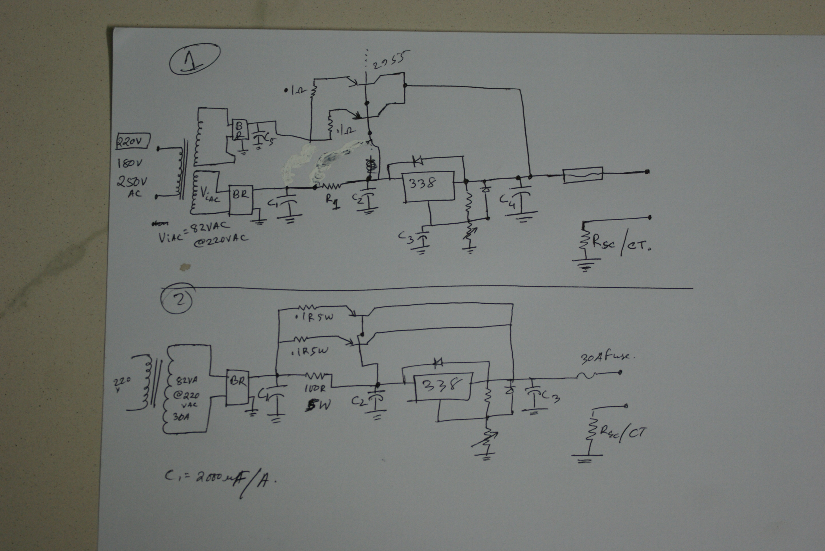
The schematic is just for a linear regulator with a bypass transistor to assist the LM317.

Each regulator is set to 24V which is fine but to get 48V you have to stack one above the other. In other words, join the ground of one to the output of the other and take your 48V from the other two connections. In this configuration you must use two isolated transformer secondaries. They can be on the same transformer or on two separate transformers but they must not connect directly to each other.

I see a problem though, assuming you are using lead-acid batteries, the charging voltage needs to be about 55V. If you really need a steady 30A, you will need transformers rated at no less than 1.7KW which will be big and heavy.

Remember that you cannot defy the laws of physics, it makes no difference whatsoever if you use BJT or FET devices in a linear regulator. Your intention is to convert unused energy into heat and the amount will be the same regardless of transistor type.

I'm not sure what you think you will gain by using an LM338 instead of an LM317. The transistor is to carry the excess current that the regulator can't handle so it does most of the work. You would share the current slightly better but the overall power would be the same.

Brian.
 

Re: MOSFet Bridge Rectifier problem...

Dear Brian sir,
Well, 338 says that it is a floating regulator... so all i need is to keep Vi-Vo in 35V (In my case, i choose 30V). So my calculation for 180VAC (the lowest allowable) is 67.2 (48*1.4=67.2 and for boost and float, i need 14.4*4=57.6 and 13.8*4=55.2). So enough voltage there... and normal voltage 220VAC will produce 82.1333V (I used the math 220/(180/67.2)) and for max 250VAC, 93.33V. So the max 93.33 is only gets to the edge... (I am looking for another regulator that can solve this over voltage problem, but i'm in doubt if it is available in market here). Basically since for my requirement, 338 works (as per datasheet), i am planning to use it. and the 2955 for passing the more current i need. I am posting a schematic here that i am planning for (modified version of the last image i posted). Basically it is same instead there will be a .1R 5W at the emitter of 2955 for current limiting (5A) and i can cascade multiple 2955 for required current. And in that case, can i use the same trafo or another transformer??

(note that i was planning for a 48V SMPS system but that seems real hard in my place due to availability of components and my lack of knowlegde)

About the size of TRAFO, if i could make it with 24V, that would be the easiest thing for me... but i need to charge almost 1000VA within around an hour... so 48Vx20A will give 960VA (assume) and my system bank will have around 48vx200AH = 9600VA. But i will consume around 1 to 2 KVA. so my power outage will not become a disaster for me... (As now i get 1 hour power and 1 hour no power from my utility)...

48V20A trafo is BIG. but with the consideration of 24V, same VA, isn't it small?? Also i need to run an inverter with this battery bank...

Mishu~

Added after 30 minutes:

And please tell me which one sould i use?? (In the case of 338 ofcourse)... and if there any correction needs...


Added after 1 hours 40 minutes:

at https://www.epanorama.net/phpBB3/viewtopic.php?f=3&t=1284 i founf another approach... but i am not sure wheater i should use it or not...


Re: MOSFet Bridge Rectifier problem...

LM317 is also a floating regulator so it should work equally well. Floating just means it isn't tied to a fixed voltage, ground in this case.

Schematic 1 will not work, it isn't possible to control the transistor conduction properly to stabilize the voltage.

Schematic 2 is correct but the values are wrong. It works like this:

At low currents, the output is provided ONLY by the LM338. Current passes through the 100Ω resistor then through the LM338 to the output connection. The LM338 controls it's own conduction to maintain regulation. As the current increases, the voltage dropped across the 100Ω resistor also increases until it reaches the base-emitter turn on voltage of the transistor. From then on, any additional current causes the transistor to conduct more rather than the extra current going through the LM338. So the value you have as 100Ω is much too high, it will drop Vbe (I'll use 0.65V as Vbe) when the current is only 6.5mA. In other words the LM338 will only carry 6.5mA and the transistor will carry the rest.
I would suggest you pass 4A though the LM338 before the transistor turns on so the value should be changed from 100Ω to (R= V/I) = 0.65/4 = 0.15Ω.

The other thing that looks wrong is your transformer rating. If we assume for 48V out that you are using 60V at the transformer secondary, instead of 82VA the actual rating is 50V x 30A which is 1500VA.

If all you want to do is charge batteries as fast as possible, it would be easier, although no technically the right thing to do, to simply use series resistors to limit the current directly from the bridge rectifier. You don't need to regulate it at all and you don't need it to be 'clean' DC either so you could leave the capacitors out as well.

Look at it this way, if you wanted the final charge current (battery fully charged) to be 1A, work out the series resistor that lets 1A through when the battery is at full voltage. You may have to experiment to find the right value. If the battery is below full charge, more current will flow which is what you want. The resistor may need to be high Wattage rating but you can make your own if necessary.

Brian.
 

Re: MOSFet Bridge Rectifier problem...

well, brian sir,
About the charging, I know here some cheap manufacturers use just 2 mosfet as rectifier and directly feed them to battery. No regulation and just a BIg voltage fed in to the batt. This somehow makes the batt charged fast but dries the batt. I want to implement the boost and float charging mechanism (as i made earlier for my 12V SLA batt). Thus it can take good care of my battery. Currently i am siffering from drying batteries...

So i need a good charger at 48V 30A rated. SMPS is good but not available here. And linear is easy to make but not efficient... So i'm in a middle of what to do... And still every moment, i am suffering from power outage... (Ohh... my goal is to make a rack mountable one...)

I'll do study on your topic and will give feedback soon... and abot current monitor, can i use CT here??
 

Re: MOSFet Bridge Rectifier problem...

According to this source, the fet rectifier circuit has a drawback - It isn't suitable for connecting a capacitor to flatten the dc voltage.

Reason: unlike diodes, the fets will conduct both ways.
 

Re: MOSFet Bridge Rectifier problem...

Prototyp_V1.0 said:
According to this source, the fet rectifier circuit has a drawback - It isn't suitable for connecting a capacitor to flatten the dc voltage.

Reason: unlike diodes, the fets will conduct both ways.
Currently in the planning of using high current bridge (As i got a 80A bridge). But need to make a 48V 30A PSU. input range 190V-250V.

Added after 11 minutes:

dear brian sir,
about that 100ohm resistor, well, my personal experience is in general lm338 can not give good 4A cont (unless extreem cooling arranged). thus i am planning to let only 2A to pass. The rest 30A (30+2 = 32 is equal to 30 here) will pass through the 2955. and each 2955 will carry 5A max. thus they will last long and run cool. (though total heat will be same, but due to heat, the hfe will change and it will not affect that much). Thus 338 needs to pass 2A and 2955 needs to pass 5A. so what will be the resistor values with watt?? And If the transformer is okey for me, i mean size, then can i proceed with it??

Also please let me know if you have a simple solution with smps (as parts are not available here, specially the transformer) for the same matter. I have done some study on smps and liked it... but due to complexity and availability, i'm currently sticking on linear... also hybrid is allowed here...

Mishu~

[and what about that design?? the cascading one?? then i can use pc psu with mod to charge them... each 12v bank with one charger and total 4 chargers...]
 

Re: MOSFet Bridge Rectifier problem...

Dear Brian Sir,

according to your last post, (Vbe = 0.65V), I am planning for 0.5ohm 5w for a safe current flow through 338. (this is due to as i am already using it and found that at high temp, it doesnt work well... and thus i am not planning to use any cooling fan for it other than a heat sink. (the special cooling and heat sink will be used for the 2955s.). So 1-2A current is ok... as this current will keep this stable and good for long time...

Note: About my previous charger, It is working just fine (but 2 stage, where i want now 3 stage for my IPS). all i had to do last night is changing the bridge for a bigger current (kbpc 808). Now it is stable at 3-4A. where it was not stable previously at current > 1A.

Mishu~

PS. Can you describe a bit more elaborately on the stages of charging a Lead Acid battery in 3 stage? ofcourse please do not calculate per cell, but consider directly 12V or better 48V.
 

Re: MOSFet Bridge Rectifier problem...

Guys, Did a lot of study (and sick again due to study but not eating that much, as usual) on battery charging again... on www.batteryuniversity.com and found some good info... now all i need is a uC to measure the terminal voltage and then feed the current first... by the same time, i have monitor the terminal voltage.. at 80-90%, i'll give flat trikle charge and at current consumption less than 2A (in fact i need to check for 1A), it will switch for float... hope this way, the battery will charge fast and run longer... both...

Now i need to develop the ckt. hope, i can... i'll update soon... (after i become ok and ready to be sick again....)

Mishu~
 

Re: MOSFet Bridge Rectifier problem...

guys,
i got an idea on a combination of constant current first then const voltage... but need some ans before i can draw the ckt.

I can use a relay for this job... around 1A max will be passed through the relay... now i have the relay that drives by 12VDC. It is printed for load as...

220VAC 10A
28VDC 10A

These are the max load for this relay... now if i use say around 60VDC but only 1-2A, will it work???

Mishu~
 

MOSFet Bridge Rectifier problem...

Please start another tread for this question. Constant voltage/current has nothing to do with your first question.
 

Re: MOSFet Bridge Rectifier problem...

You should consult the manufacturers data sheet to check. The AC voltage rating is much higher than the DC one because if an arc is drawn when the contacts open, it will extinguish at the next zero voltage crossing point. A DC arc will continue to burn and can do more damage to the contact surfaces. At higher voltage there is more chance of an arc forming, only the manufacturers tests will confirm if 60V is too risky.

Brian.
 

understood... catching manufacturer from here... hard job.. but i'm trying... mean while, doing ta little lab test by myself... planning of feeding a 48V but 1A where the relay is rated for 30V 10A DC. let's see what actually happens... it's clear and i can see everything if it wear/tear...

also if i really fail, then propably i'll have to arrange a battery charger for 48VDC bank commercially that is rack mountable...

Anyway... i'm now planning for a little less version... 24V bank... if, then again need the const current-->const Volt--> float volt mode charger that needs to be home made... (as some thing i always want to develop)... so i'm in a thinking of a thing... using one single regulator... (i'll post the schematic of my idea for in dept what happes to know...) and if i fail that one, then i have to go for two regulator for one is for const current and rest for const volt... relay again needed here... but this time, it will support the voltage and current rating...

mishu~
 

Guys,
Can you tell me one thing?? I have observed (using my small 200VA inverter for laptop with some load) that when I connect a fully charged battery, the terminal voltage is around 12V. then after taking low load, it stays at around 12V. but when i am taking a large load, it drops.... first of all, what is the reason behind it?

Next thing that currently i am experiencing with my house's commercial Instant power supply (IPS) is when it delivers power, then it can detect the peak current flowing and trips on that for preventing over load. I also can do that with a timing of 3 sec allowed for over load. but in commercial IPS, when overload happens, it trips, and then when load gets reduced, it ONs again... (I dont want that... i wish to make a manual reset there...)
Also when the battery voltage gets low, but still there is load conencted, it trips... then it kept off for a while... this time, the voltage in battery rises after a time and once it increases it again gets ON. but since there is a load, the batt voltage falls below threshold again and it trips off again... it continues... ON-OFF-ON-OFF.... but i want to prevent it... i want to allow this low voltage operation for some more time (instead of ON-OFF-ON-OFF) and want to shut the system (standby for manual reset/waiting for mains back) for that time... so that the system's unstability (that currently has in commercial IPS) will be reduced... any ideas???

consider 12V here... (as we can scale that to desired voltage later on...)

Mishu~
 

Hi Mishu~

First part:

200VA is a big inverter for a laptop - mine uses 60W maximum! For some reason it doesn't seem to be able to produce full power at high loads. Exactly why is very difficult to predict. If it used to work but is slowly losing output, I would suspect the capacitors in the inverter were dropping in value. If it has always done this, check what type of inverter it is. Some inverters produce square wave or modified sine wave outputs which may measure correctly on a voltmeter but have waveforms which are less useable by the load.

Second part:

The IPS sounds like it isn't designed for use where the battery can fluctuate so much. There is a very simple circuit you can add outside the IPS so it trips and stays off until you manually reset it. I can't draw diagrams at the moment so I'll try to describe it, there are only three components:

Use a double pole relay with contacts rated to handle your load.
Wire one pole in series with the relay coil and wire a push-button 'start' switch across this set of contacts, the other side of the switch/contact is your incoming supply.
Wire a diode across the relay coil so it is NOT conducting (cathode to +). If you change from DC to AC, omit this diode!
Finally, wire the other set of relay contacts between incoming supply and your load just as though it was an ordinary off/on switch.

The idea is that the relay is NOT energized because it's own coil is disconnected by it's own contacts. At the same time the other set of contacts are isolating your load. When you press the switch, the coil energizes, this does two things, it turns the load on and it bypasses the push button so the coil stays energized when you stop pressing it. So it stays on by itself - until the power is interrupted, then the relay contacts open and cannot close again until you press the button once more.

Technically, it's called a 'Contactor' circuit and you find it used in industry where for example machinery must stay powered down after a black-out until someone is there to supervise while it is started again.

If I didn't describe it well enough, let me know and I'll draw a diagram later.

Brian.
 

sir, sound great... but thing is currently my home IPS is doing the on-off when it reaches under say 11V, it gets off... and after remaining off for a while, when voltage rises, it ons again... and then again voltage drops... so this process continues... i want to stop it... so whn batt is low, it'll off... and batt will rise... but it will not on again... but may be for a 2 sec or so, it may go below 12, even 11... but i will let it run... say for 5 sec if it still at 11v, then it'll trip and wait for manual reset... will it be oky??? i wanna then use the uC and software that case... (in most of the time, reset is the system reset and it'll reset the whole system... including charger, changeover, inverter... (one single reset sw for all>..)..

Mishu~
 

Mishu, why not consider using controled bridge rectifier with thyristors - it will do the entire job : controling voltage, current, etc. I've seen such implemented with 2 diodes and 2 thyristors - diodes for + and thyristor for - . Control circuit was very simple, pure analog with some thransistors (extreamly cheap and common) R's and C's.
 

can you give me some example??? that might help me a lot...
 

Dear Brian Sir,
can you tell me one thing?? I cant figure it out...

I need to measure 30A of current through a shunt... i'll use Mega8 or mega32 ADC. 5V referance... so 30/5 = 6 [scale factor] i can use...

basically i have to measure starting from full range 30A [5V] till 500mA. Thus can you tell me what exactly should be the shunt???

Mishu~
 

If you put the shunt in the negative rail so one side of it is 0V, you can directly measure the voltage at the other side. The value to drop 5V at 30A is (R=V/I) 0.1666Ω and the power rating should be at least (V²/R) 150W.

I'm going to guess this is far too much voltage and power loss so you should consider using a smaller shunt resistance and an amplifier to increase the voltage up to 5V. It is also easier to protect the amplifier than to protect the processor in event of the shunt burning out!

Before you go further, remember that any shunt works by dropping the available voltage so work out how much you can sacrifice or whether you can regulate the voltage taking the shunt loss into account. When you know how much you can allow the shunt to drop, you can work out by how much it needs amplifying to bring it to full ADC scale.

Brian.
 

dear Brian sir,
I was working on it... and come up with it.. (as shunt makes huge loss in case of 5v scale..)

i will use software for calculation and i need high 20-30A where low 1A atleast... more less, better... but i want to reduce complexity also... so since about charging a 100-200AH battery, i'm considering of 1% of total 9so for 100ah, 1A) as full charge state and to go for float voltage... now, in this case, 1A is okey with me...

So if consider (at first...) 20A (later upgradable upto 30A), then i can use .1ohm 5w resistor total 4 nos in parallal... means

Code:
     |--vvvvvv---|
----|--vvvvvv---|----
     |--vvvvvv---|
then as per KCL, each .1ohm will carry 5A (for 20A). Now it i still stick with my previous charger with 5A equals to 500mV at shunt, then for 20A, i'll get .5V. Means as per software calculation, when ADC sees 500mV at shunt, then .5V*4 = 2.0 means 20A

Now for lower part, since 5A makes 500mV, 1A will make 100mV for one resistor, the final shunt (4||) will carry 1A where each resistor will carry .25A. As per math, for 1A, it develops 100mV (single resistor) and for .25A, it will be (0.1x0.25) = 0.025V = 25mV. This is okey for me as currently ADc can take minimum of 4.8mV. So i can even reach near to 500mA.

So do you suggest me to use a 0.1ohm||4 (as at 5A full, it only develops 500mV), altogather it will still develop 500mV at 20A.. So math will be ADC volt x 4 x 10.

Power rating 5W here...

Please suggestion.... Also about compansating with the regulator output and drop of shunt, i'll use lower side measiring and i'll have to calibrate the regulator on + and - terminal (not the + and GND) for a 13.8V calibration right??? (please tell me a bit more on this calibration..)

Mishu~
 

Status
Not open for further replies.

Similar threads

Part and Inventory Search

Welcome to EDABoard.com

Sponsor

Back
Top