Vermes
Advanced Member level 4

It is a design of a system which reads the card code via interface EM4095 with an antenna, decodes, checks and sends it through the serial port. The reader is based on Attiny13. Program takes only 782 bytes.
Electronics:
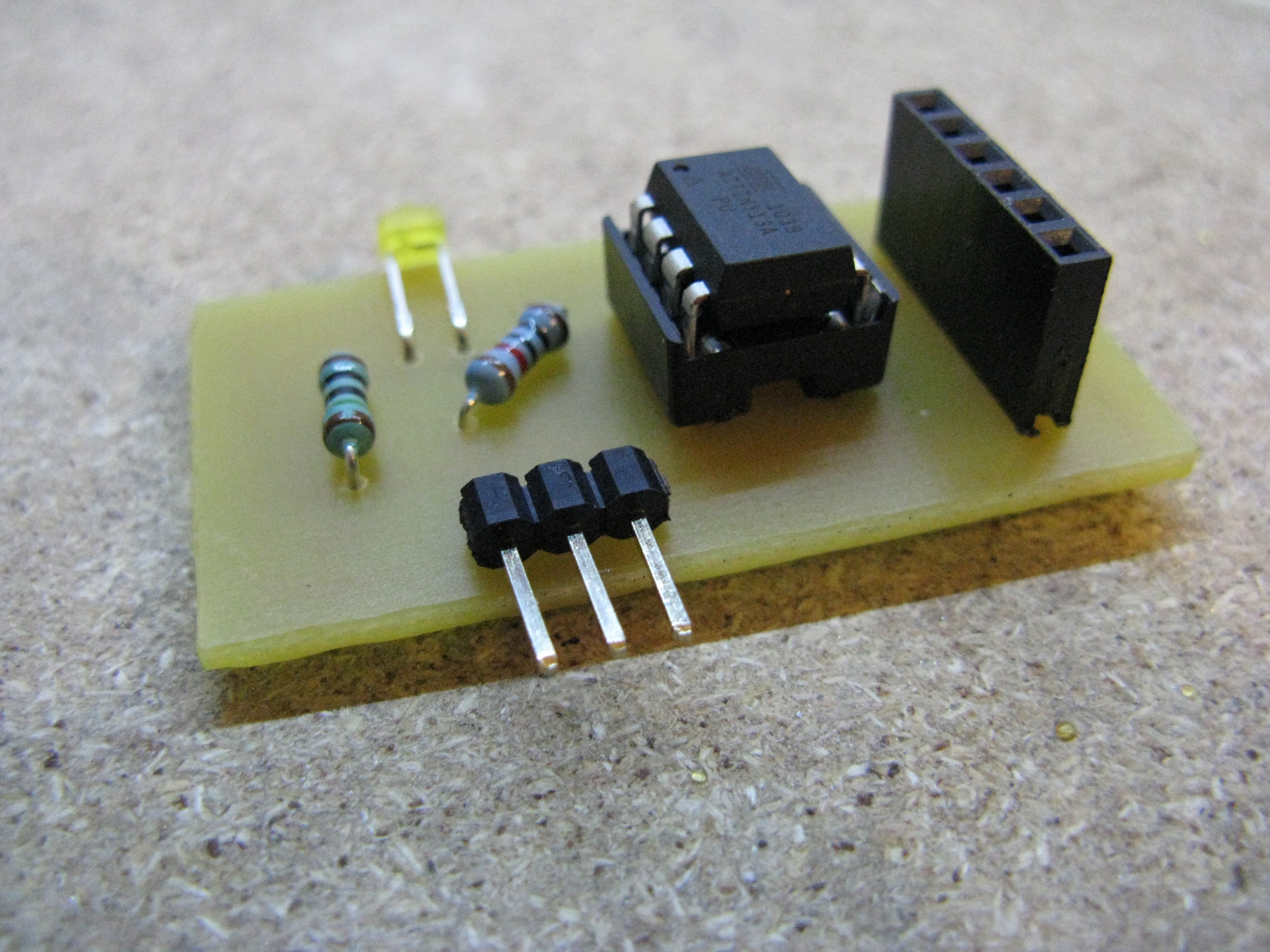
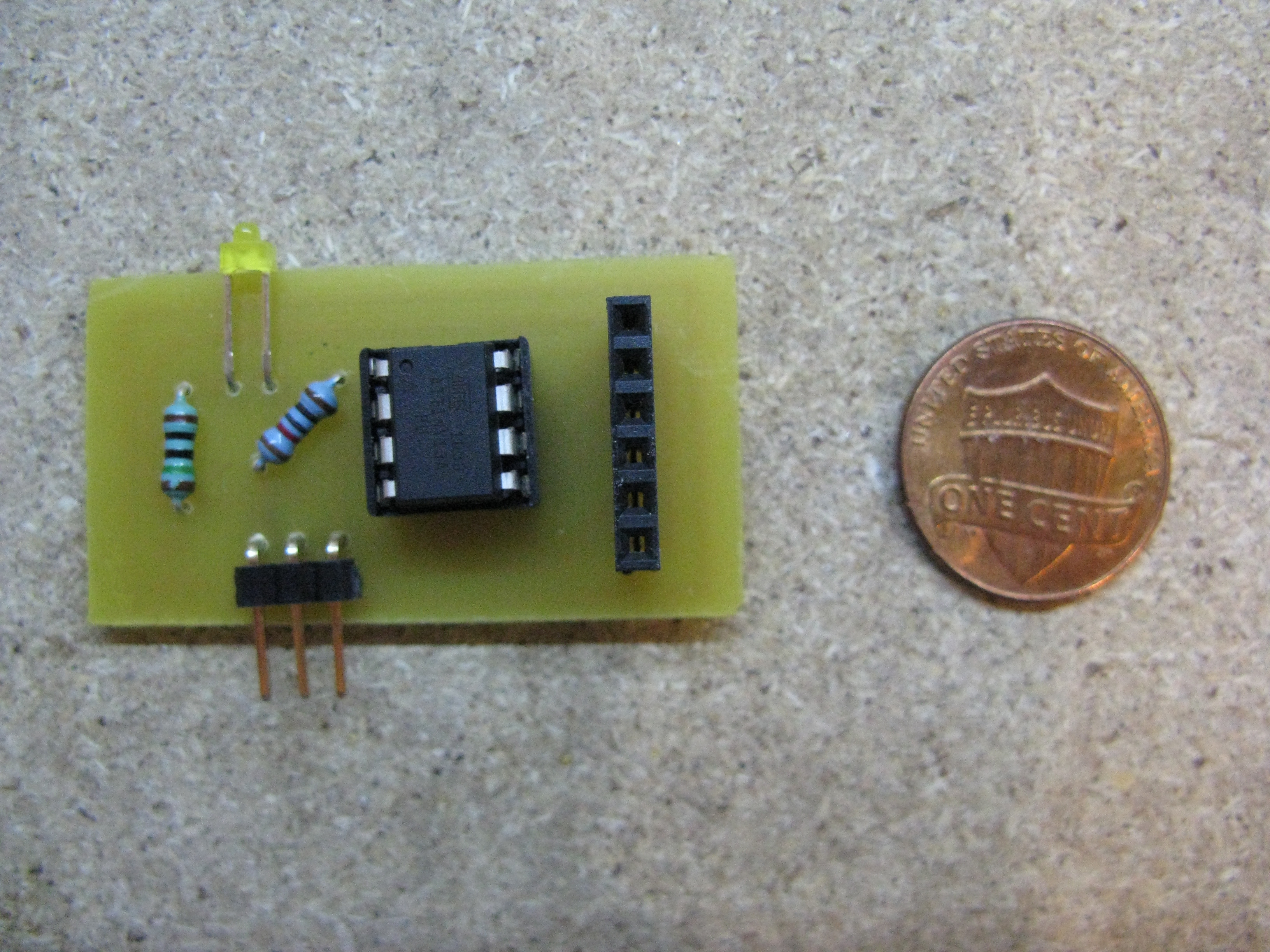
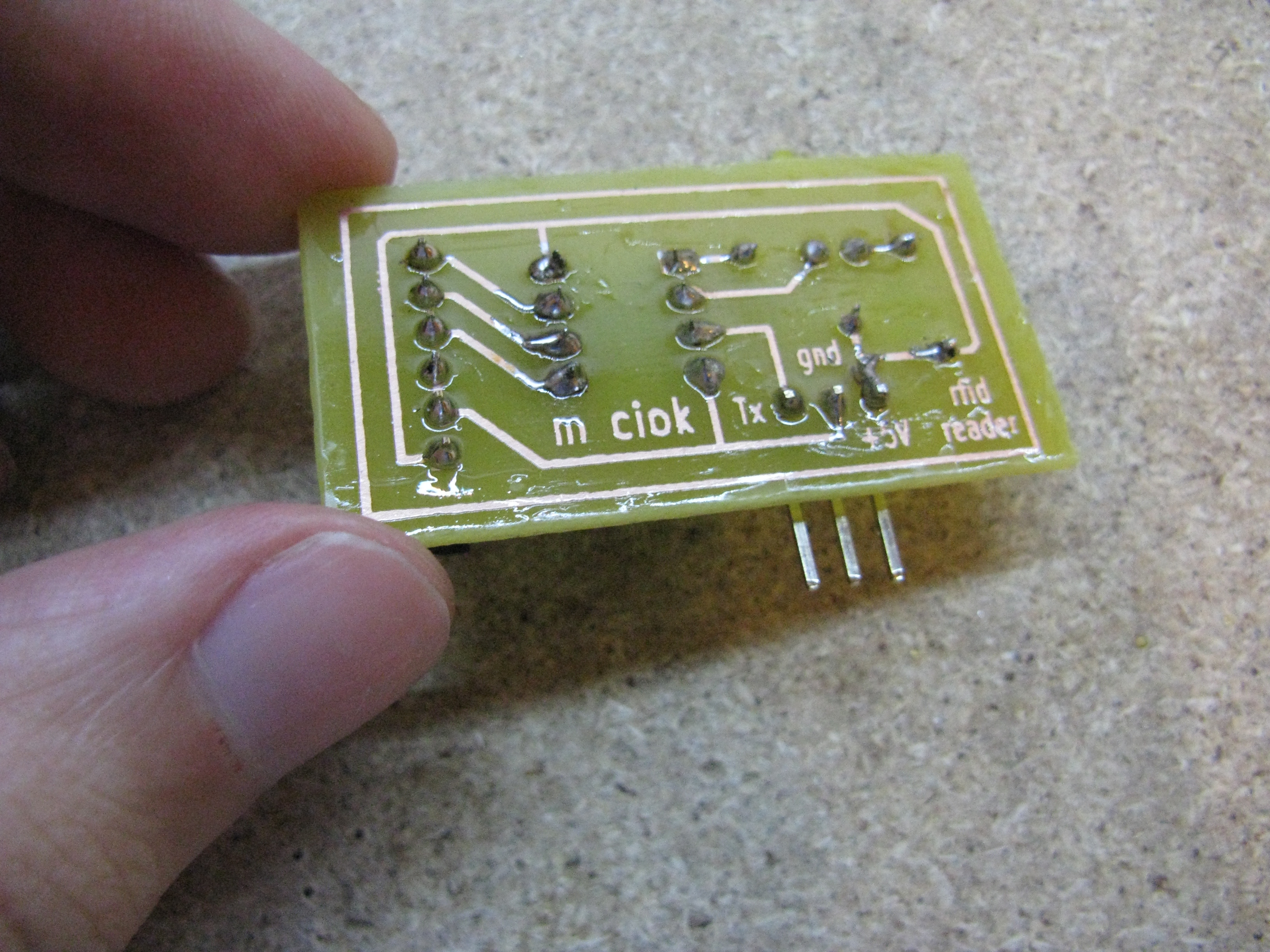
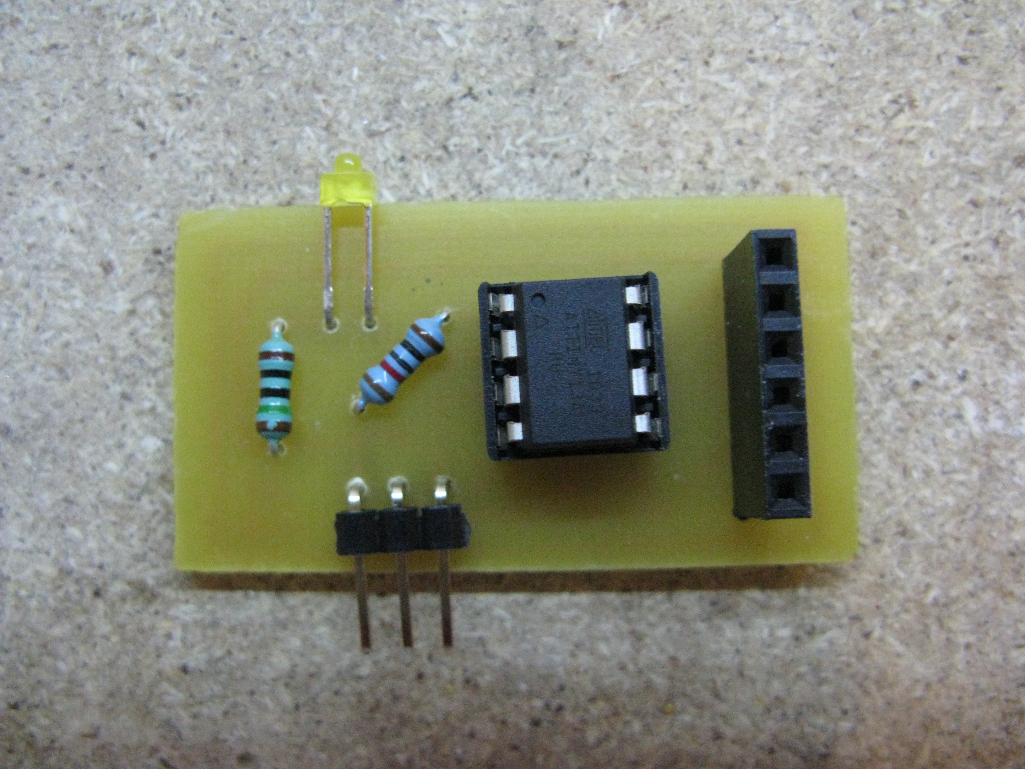
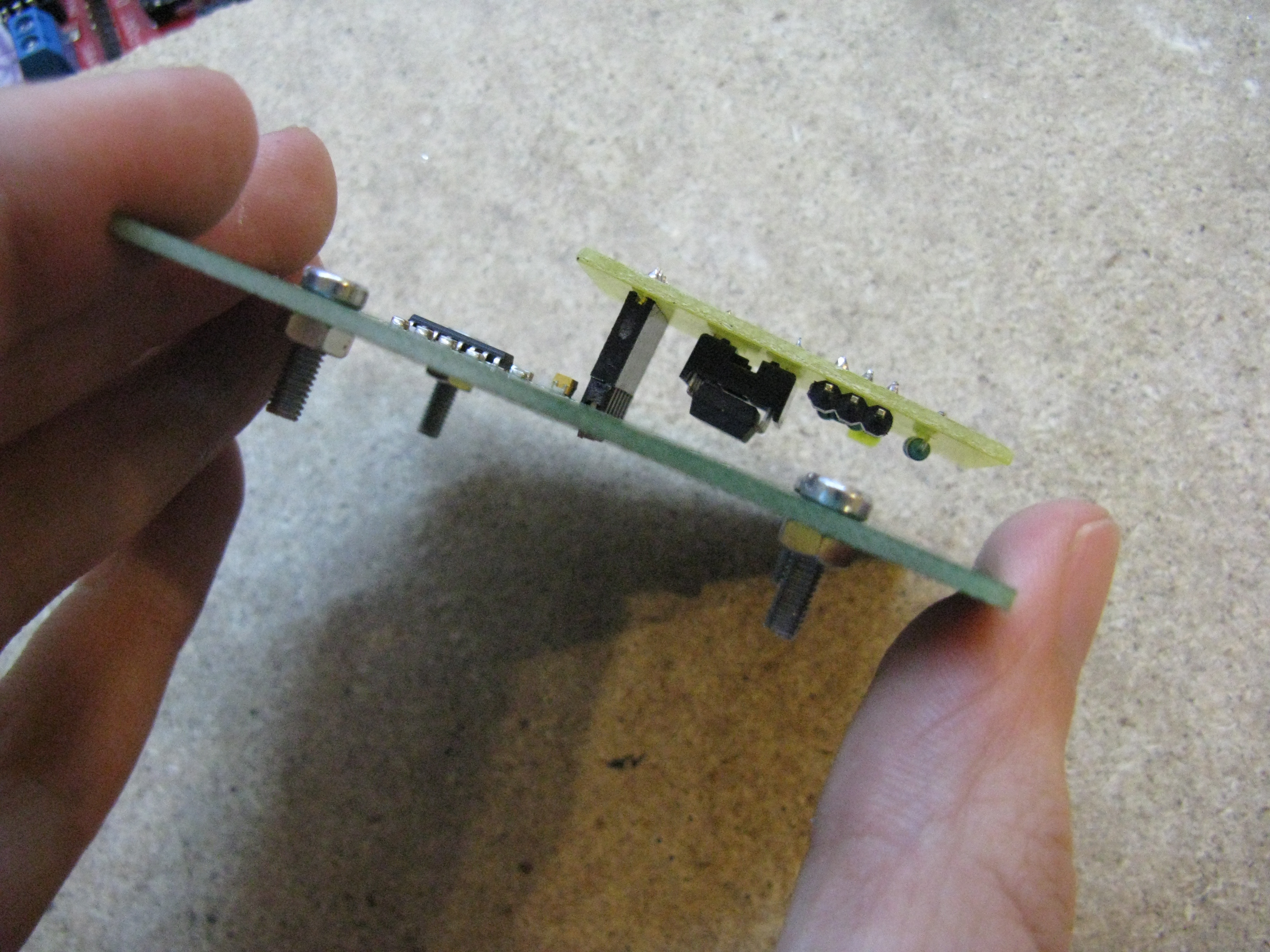
The whole was made by threaded method. Ready made interface EM4095 was used in this project because it has a perfectly chosen antenna and it is cheaper to buy a ready module. Interface is a typical circuit EM4095. Pins of analog system (MOD, DEMOD_OUT, SHD, RDY_CLK) are derived to the header strip. The system can be easily home made. The board was made by thermal transfer method, drilled by a 0,8mm drill, then painted with clear nails lacquer. The reader can be placed in the headers on the interface using FHY06 SSG PIN HEADER connector. Of course, you can use a simple header strip instead of a socket and connect other interfaces EM4095 or put everything as a part of a larger project.
Firmware – microcontroller software:
Before programming the microcontroller, the fusebits should be set properly. By default, Attiny13 has dividing by 8 enabled. This option must be disabled. If the clock is set to a different frequency than 9,6MHz, set that value. Fusebits are as follows: High fuse: FF Low fuse: 7A. If you have other values, the program can not work properly.
It is important to connect the system to interface EM4095 before you enable the supply. Program after connecting the supply initializes system EM4095 and goes into its normal mode (waiting for the card). In the case of connecting the system to the interface with enabled supply, the microcontroller will not make the necessary initialization of system EM4095 and can not receive data.
You can upload the software in two version to the reader. They have different speed of data sending via serial port. Other parameters such as the transmission protocol, terminals, etc. remain unchanged. Available speed of data transfer:
- 9600 bps
- 4800 bps
Theoretically at a speed 9600 bps and internal oscillator 9,6MHz (fluctuations 9,45-9,7MHz) transmission errors can occur (approximately 0,8%) while they should not occur at 4800 bps.
Data frame:
The reader sends 14 bytes of data.
- 1. 0x0a LF
- 2. 0x0d CR
- 3. 0x7E start of transmission of the card code
- 4.-13. hex code of the card. Each byte contains one hexadecimal digit
- 14. 0x7Cend of transmission
Serial transmission settings:
Speed: depending on the chosen program: 9600 or 4800
- Data bits: 8
- Stop bits: 1
- Parity: None
For continuous holding a card in the field of antenna, the code is cyclical sent every 0,7s.
Program was written in C (AvrStudio 4 + WinAVR-20100110) and in Assembler.
Data receiving on PC or other microcontroller:
A program receiving data from a serial port should be installed on a computer. It can be a terminal (Putty or Br@y++) or you can use your own code (as a fragment of an application).
Pictures:


Link to original thread (useful attachment) – [C] Attiny13A czytnik RFID wysyłanie kodu przez RS232


") and the sending the data to the PC through quick'n'dirty "level converor" made by 2 resistors.
and the sending the data to the PC through quick'n'dirty "level converor" made by 2 resistors.