Continue to Site

Welcome to EDAboard.com

Welcome to our site! EDAboard.com is an international Electronics Discussion Forum focused on EDA software, circuits, schematics, books, theory, papers, asic, pld, 8051, DSP, Network, RF, Analog Design, PCB, Service Manuals... and a whole lot more! To participate you need to register. Registration is free. Click here to register now.

atmega8 and l298n supply

Status
Not open for further replies.

vvarlord

Member level 4
Joined
Mar 15, 2012
Messages
74
Helped
4
Reputation
8
Reaction score
3
Trophy points
1,288
Activity points
1,756
i'm using atmega 8 for creating a pwm for a 12v motor
the pwm goes to input of a l298n and the corresponding output goes to motor
atmega works with a 5v,and i use a 7805 which its input is 12v
for the logic supply of l298n i use the same with atmega
and when i use a seperate 12v supply for the ,main supply of l298n everything works fine
but if i use the same 12v which supplys the 7805, it just stops working
i just want to use one power supply for the whole circuit
any help would be appreciated
 

what is the ampere of your power supply. It's may be low
 

i use 8 rechargeable 1.5v batteries,i don't think the problem is the current of supply of voltage
 

i use 8 rechargeable 1.5v batteries,i don't think the problem is the current of supply of voltage

to be sure the problem not from the current of power supply. Try using with power supply 1 or 2 ampere to excluded this solution and try another one.
 

i just ran the circuit with a 12v 1.2A output adaptor,still the same
 

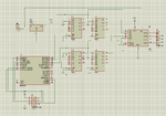
Then you can upload your schematic so we can discuss the problem ?
 

here's the schematic
by the way,tnx ffor your assitance
zzz.png
 

is your controller stop working?
 

try to add capacitor at the input of 7805 with value like 470uF and output of 7805 with 10uF. Also add 0.1uF capacitor at the vcc of ATMEGA.
 

i just added the 470uf and 10uf capacitors and it takes longer before it stops working
but the problem still exists
any other suggestion?
 

Such a configuration should work fine, and I have done so many times.

Try including the recommended caps at L298 power pins, and also include a small voltage drop resistor on the input of the 780. The value would depend on the load current of the Vcc segment.

Oh yes... make sure you connect your free-wheel diodes to your motor(s) !!! Otherwise you will get all sorts of spikes on the power line.

btw - why are you using so many muxs? You can reduce this to just 2, and maybe even eliminate them all by connecting the Atmega8 pins direct to the L298 ?!
 
Last edited:

the muxes are used to make the motor run reverse,when needed
the 4 number is also for,being able to reverse each motors seperatly
the diodes are used ,and i think it would be a matter of broken l298 IC
haven't cheked it yet,but will do as soon as possible.
tnx all of you for replies
 

the muxes are used to make the motor run reverse,when needed
the 4 number is also for,being able to reverse each motors seperatly

Well that is of course obvious. My point was you need 4 control signals to do this, and these 4 signals you already have available direct from the uC. So why add extra 4 IC's !?
 

in your case , i need 4 pwm lines but atmega8 has only 2 lines.
 

Oh i see. You are running 4 motors, all 4 with speed control and direction reversal capability. I thought you were running two motors in full H-bridge config.
My bad.
 

i'm runnig two motors
and in matter of fact when you want to control two motor and give them the reverse capability,you have to be able to turn the two poles of each motor
but when you use one of the two pwm pins of micro, as an input of l298n to control the motor,you will only be able two run it in one direction,since you can not turn the poles.
so i used the muxes to change inputs of l298n and therefore the poles of motors
 

Oh actually you can. There are 2-3 ways to do this. Each has its own small tradeoff.

1) you feed the PWM to the ENA pin, and single pin Fwd-Rev/ signal to Inp1 and Inp2. i.e. use a inverter between IN1 and IN2.
2) feed PWM to IN1, and the Direction line to IN2. This requires you to change the duty cycle of the PWM whenever you change Direction if you want the speed to remain the same. i.e if your duty cycle was 20%, then on direction change you make it (100-20) 80%
3) feed PWM to ENA, and use 2 pins for direction control fed to IN1 and IN2. This requires an extra pin from uC, but gives the power to fully control the motor speed, direction, braking etc etc.


But in all cases make sure you put in ALL the fre-wheel diodes !!
 

well ,haven't thought about it this way
if it doesn't bring up limited frequency issues , it would save 4 muxs
really appreciate your help
 

Status
Not open for further replies.

Similar threads

Part and Inventory Search

Welcome to EDABoard.com

Sponsor

Back
Top