shaikss
Full Member level 4
Hi,
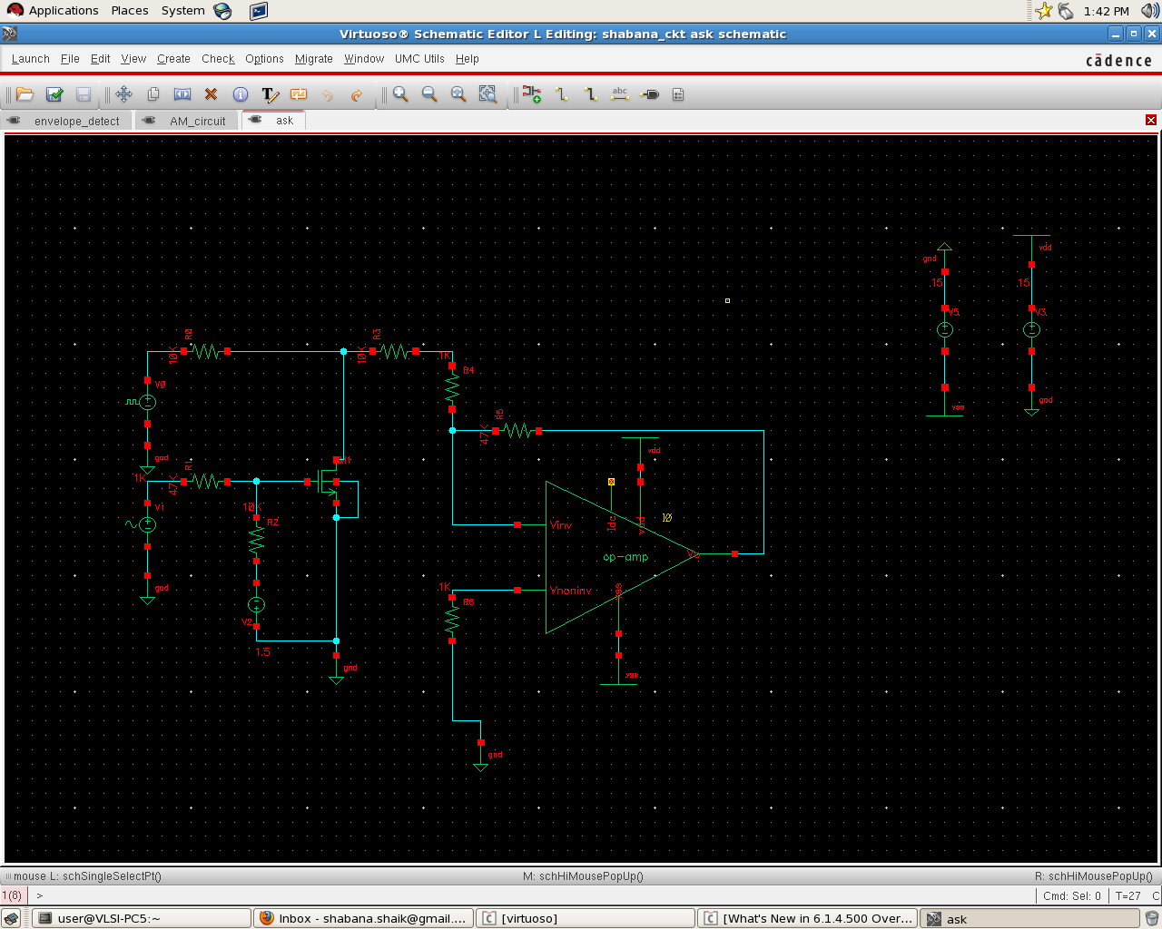
Attached is the snapshot of the schematic of ASK modulator.
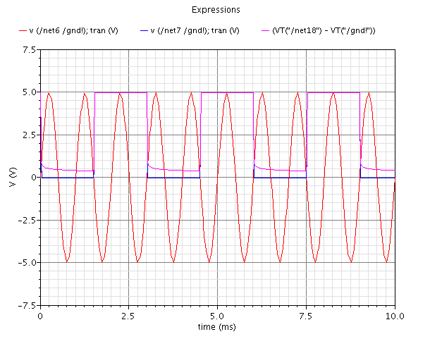
I have attached the plot too.
I am not getting where the mistake is but I hadn't get the desired output.
Please correct me and help me to get the desired ASK modulated output.
Thanks!
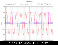
Attached is the snapshot of the schematic of ASK modulator.
I have attached the plot too.
I am not getting where the mistake is but I hadn't get the desired output.
Please correct me and help me to get the desired ASK modulated output.
Thanks!