Continue to Site

Welcome to EDAboard.com

Welcome to our site! EDAboard.com is an international Electronics Discussion Forum focused on EDA software, circuits, schematics, books, theory, papers, asic, pld, 8051, DSP, Network, RF, Analog Design, PCB, Service Manuals... and a whole lot more! To participate you need to register. Registration is free. Click here to register now.

Any good free software to draw logic signals

Status
Not open for further replies.

Sink0

Full Member level 6
Full Member level 6
Joined
Nov 25, 2009
Messages
390
Helped
37
Reputation
74
Reaction score
30
Trophy points
1,308
Location
Sao Paulo, Brazil
Activity points
4,186
When i am making a project with verilog, draw the logic states help me a bit. But drawing by hand is a bit tiring.. For now i am using Excel.. but i am sure there is some program i could use for that. Which program is used on the datasheets to show the functionality of some circuits?

thank you!
 

Its most dependent on the FPGA itself.. ISE for Xilinx and Quartus II for Altera.
 

Prior to ISE v11.1, Xilinx provide StateCAD which allowed you to create state diagrams which could then be imported into the ISE Project and implemented into Verilog or VHDL.


Unfortunately, it has been removed on release v11.1. You can however still use the language template feature to implement a state machine.

I'll see if there are any alternatives available.

Quartus II may still have a similar feature, although I have not used it.

---------- Post added at 21:52 ---------- Previous post was at 21:44 ----------

Trying using WinFIG and covering it with brusey20 to HDL.

**broken link removed**

Although it apparently only supports VHDL export.
 

Thank you for all the help.. but what i need is more simple than that.. i dont need any conversion.. jsut sometool to draw digital timing diagrams. It is just to organize my mind while i am programing. I am going to draw the behavior that i want, and write the code for that... there is not need for automatic conversion.

Thank you!
 

On the subject of using visio for that sort of thing ... are there any good stencils for logic design + dsp pipelines and such. No doubt visio has some standard flipflops, but I also mean things like adders, accu, etc.
 

You can use OpenOffice Draw:Its a Freeware and you can do all the drawing you need for state machines etc....
 

For drawing relatively simple fsm's you can use Qfsm.
 

the exact name of the program that is used in datasheets is not known.
for me , atleast , i couldnot get the name of the tool.
but given the nature and quality seen it can be only a tex based . this is my wildguess.
since you mentioned Tikz i think you can write simple scripts for such task.

Tikz is very good but... you must be a tex/latex user already.

or if you are a linux user you can try 'Drawtiming'.
 

Free online logic timing diagram editor, specifically for VHDL and Verilog:

**broken link removed**

**broken link removed**
 
  • Like
Reactions: Sink0

    Sink0

    Points: 2
    Helpful Answer Positive Rating
The second one was wht i am looking for. Is a demo version so i dont know if it will eventually expire.. but i will see.

thank you!
 

Have a look at this thread:
https://www.edaboard.com/threads/5817/
and download the attachement named: andytime.zip
It is a freeware without sources, which produce very simple timing diagrams, simple, but can save us hours of using Visio.
 

**broken link removed**

WaveDrom is Free and Open Source online digital timing diagram editor that uses JavaScript?, HTML5 and SVG to render WaveJSON input text description into vector graphics.

The project is in progress. Any feedback appreciated.
 

Hi folks

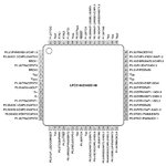
Anyone knows how can I draw an IC Pin Configuration, as shown in the attached pic, using LaTeX?

FOmKp.jpg
 

Status
Not open for further replies.

Part and Inventory Search

Welcome to EDABoard.com

Sponsor

Back
Top