I14R10
Full Member level 3
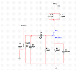
Can you help me and take a look at this amplifiers? They are supposed to be antenna preamplifiers. On the left side is my calculated FET amplifier. On the right side the drain resistor is replaced with LC circuit that resonates on 14MHz. Yes I know, the input is 14.25MHz. I calculated it by mistake for 14MHz, but it's not important. The input signal is in reality coming from the antenna connected like L1/L2 in this schematics attached below. I also have a capacitor parallel with L2.
What I want to ask is: I want to use the circuit on the right side of my schematics because it has higher gain, but I don't know if it will work. Did I design it correctly? Do you have some improvements that I could put inside my schematics? I'm building a 14MHz receiver and this is really the most important part of the entire radio.
What I want to ask is: I want to use the circuit on the right side of my schematics because it has higher gain, but I don't know if it will work. Did I design it correctly? Do you have some improvements that I could put inside my schematics? I'm building a 14MHz receiver and this is really the most important part of the entire radio.
Attachments
Last edited by a moderator:


